Wiring Examples
10-11
10
Wiring Examples
This section provides wiring examples to connect a Braking Unit and other peripheral devices to the main
circuits, examples of wiring a transformer to Inverter I/O, and other aspects of Inverter wiring.
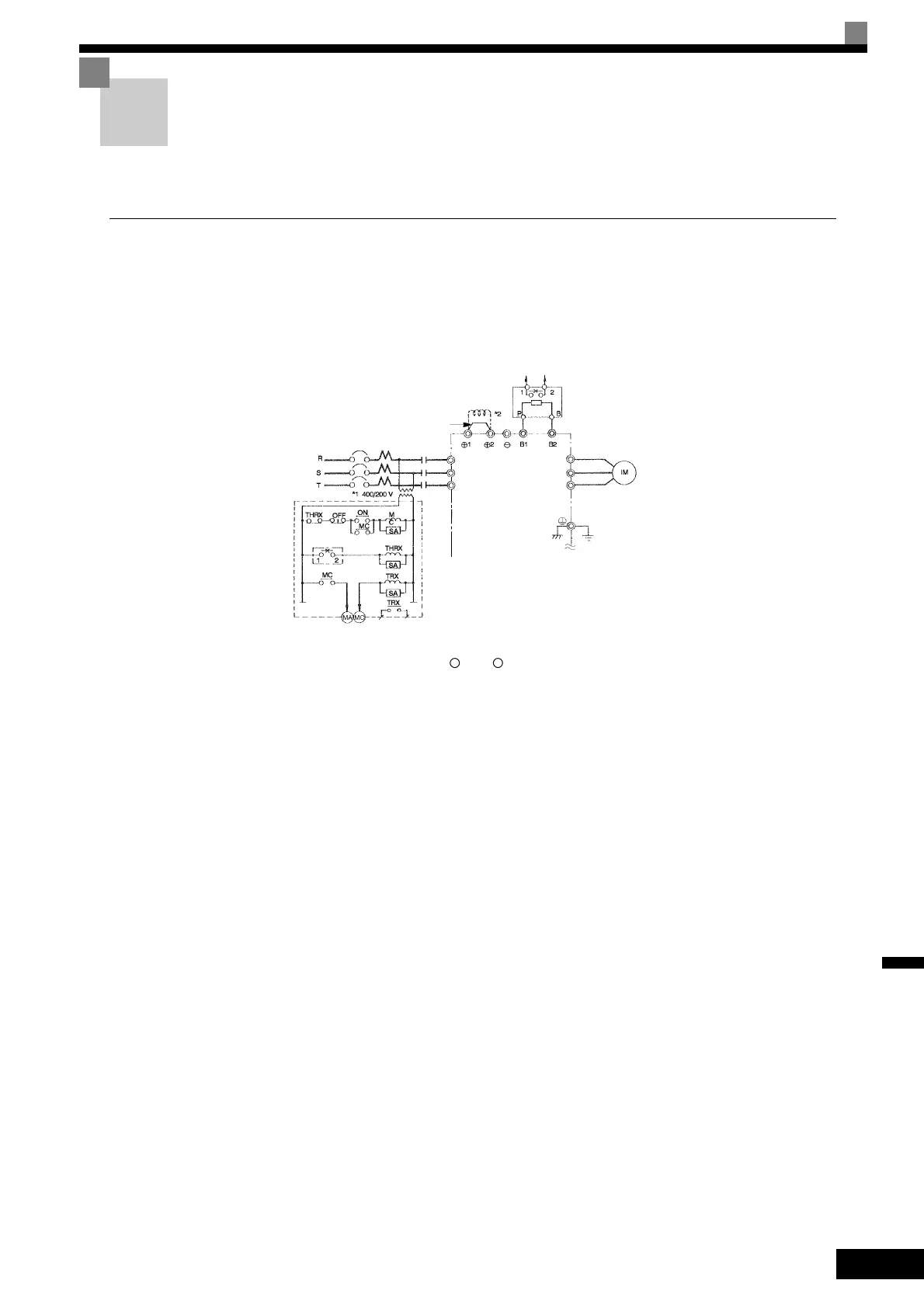
Using a Braking Resistor Unit
This example shows wiring for a Braking Resistor Unit.
CIMR-G7A20P4 to -G7A2015 (200 V Class Inverters of 0.4 to 15 kW)
CIMR-G7A40P4 to -G7A4015 (400 V Class Inverters of 0.4 to 15 kW)
* 1. A transformer is not required for 200 V Class
* 2. Remove the short-circuit bar (normally connected) from 1 and 2 when connecting a DC Reactor (Optional).
* 3. Disable stall prevention during deceleration by setting L3-04 and using a Braking Resistor Unit. The motor may not stop within the decel-
eration time if this setting is not changed.
Fig 10.6
3-phase power
200 to 230 V 50/60 Hz
or 380 to 460 V
50/60 Hz
A sequence is required to turn
OFF the power supply for the ther-
mal overload relay trip contacts of
the Braking Resistor Unit.
Short-circuit bar
DC Reactor to
improve input
power factor
(Optional)
Braking Resistor overheating contacts
(Thermal overload relay trip contacts)
Braking Resistor Unit
*3
Inverter
Overload relay trip contact
of Braking Resistor Unit
Fault contacts
Motor
200 V Class Inverters: Ground to
100 Ω max., 400 V Class Inverters:
Ground to 10 Ω max.)
R/L1
S/L2
T/L3
U/T1
V/T2
W/T3
MC
+ +

 Loading...


