4-4
Checking the Display Status
If the Digital Operator's display at the time the power is connected is normal, it will read as follows:
When an fault has occurred, the details of the fault will be displayed instead of the above display. In that case,
refer to Chapter 7 Troubleshooting. The following display is an example of a display for faulty operation.
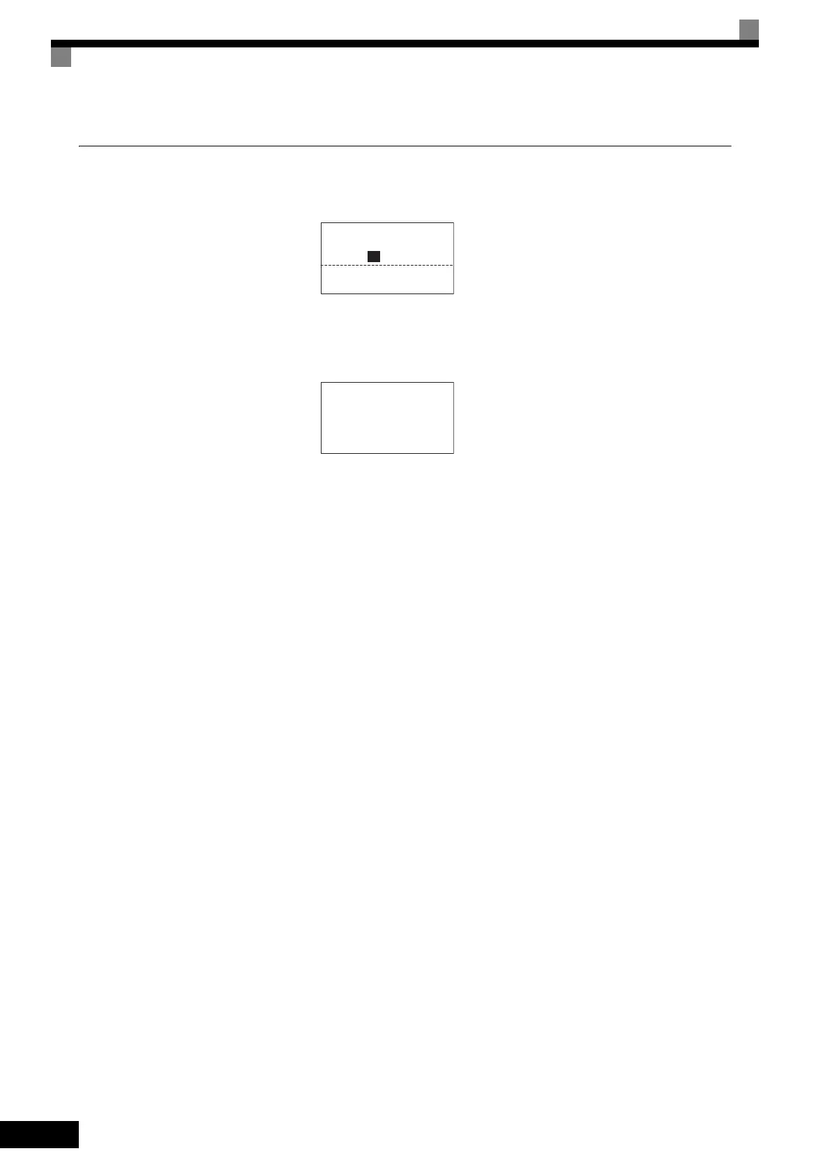
Display for normal operation
The frequency reference monitor is dis-
played in the data display section.
Display for fault operation
The display will differ depending on the
type of fault.
A low voltage alarm is shown at left.
-DRIVE-
Frequency Ref
U1-01= 0 0 0.0 0Hz
-DRIVE-
Rdy
Frequency Ref
U1- 01= 60.0 0Hz
U1-03=10.05A
U1-02=60.00Hz
01
Frequency Ref
-DRIVE-
UV
DC Bus Undervolt

 Loading...


