User Constants
10-23
10
H3-01
Signal level selection (terminal
A1)
0 L1-05
Motor temperature input filter time
constant
0.20
H3-02 Gain (terminal A1) 100.00 L2-01 Momentary power loss detection 0
H3-03 Bias (terminal A1) 0.0 L2-02
Momentary power loss ridethru
time
0.1
*5
H3-04
Signal level selection (terminal
A3)
0 L2-03 Min. baseblock time
0.2
*5
H3-05
Multi-function analog input (termi-
nal A3) function selection
2 L2-04 Voltage recovery time
0.3
*5
H3-06 Gain (terminal A3) 100.0 L2-05 Undervoltage detection level
190
*7
H3-07 Bias (terminal A3) 0.0 L2-06 KEB deceleration time 0.0
H3-08
Signal level selection (terminal
A2)
2 L2-07 Momentary recovery time
0
*12
H3-09
Multi-function analog input (termi-
nal A2) function selection
0 L2-08
Frequency reduction gain at KEB
start
100
H3-10 Gain (terminal A2) 100.0 L3-01
Stall prevention selection during
accel
1
H3-11 Bias (terminal A2) 0.0 L3-02 Stall prevention level during accel 150
H3-12 Analog input filter time constant 0.03 L3-03 Stall prevention limit during accel 50
H4-01 Monitor selection (terminal FM) 2 L3-04
Stall prevention selection during
decel
1
H4-02 Gain (terminal FM) 1.00 L3-05
Stall prevention selection during
running
1
H4-03 Bias (terminal FM) 0.0 L3-06
Stall prevention level during run-
ning
160
H4-04 Monitor selection (terminal AM) 3
L3-11 Overvoltage inhibit selection 0
H4-05 Gain (terminal AM) 0.50 L3-12 Overvoltage inhibit voltage level
380
*7
H4-06 Bias (terminal AM) 0.0 L4-01 Speed agreement detection level 0.0
H4-07
Analog output 1 signal level selec-
tion
0 L4-02 Speed agreement detection width 2.0
H4-08
Analog output 2 signal level selec-
tion
0 L4-03
Speed agreement detection level
(+/-)
0.0
H5-01 Slave address 1F L4-04
Speed agreement detection width
(+/-)
2.0
H5-02 Communication speed selection 3 L4-05
Operation when frequency refer-
ence is missing
0
H5-03 Communication parity selection 0 L5-01 Number of auto restart attempts 0
H5-04
Stopping method after communi-
cation error
3 L5-02 Auto restart operation selection 0
H5-05
Communication error detection
selection
1 L6-01 Torque detection selection 1 0
H5-06 Send wait time 5 L6-02 Torque detection level 1 150
H5-07 RTS control ON/OFF 1 L6-03 Torque detection time 1 0.1
H6-01 Pulse train input function selection 0 L6-04 Torque detection selection 2 0
H6-02 Pulse train input scaling 1440 L6-05 Torque detection level 2 150
H6-03 Pulse train input gain 100.0 L6-06 Torque detection time 2 0.1
H6-04 Pulse train input bias 0.0 L7-01 Forward drive torque limit 200
H6-05 Pulse train input filter time 0.10 L7-02 Reverse drive torque limit 200
H6-06 Pulse train monitor selection 2 L7-03 Forward regenerative torque limit 200
H6-07 Pulse train monitor scaling 1440 L7-04 Reverse regenerative torque limit 200
L1-01 Motor protection selection 1 L7-06
Integral time setting for torque
limit
200
L1-02 Motor protection time constant 1.0 L7-07
Control method selection for
torque limit during acceleration
deceleration
0
L1-03
Alarm operation selection during
motor overheating
3 L8-01
Protect selection for internal DB
resistor (Type ERF)
0
L1-04
Motor overheating operation selec-
tion
1 L8-02 Overheat pre-alarm level
95
*5
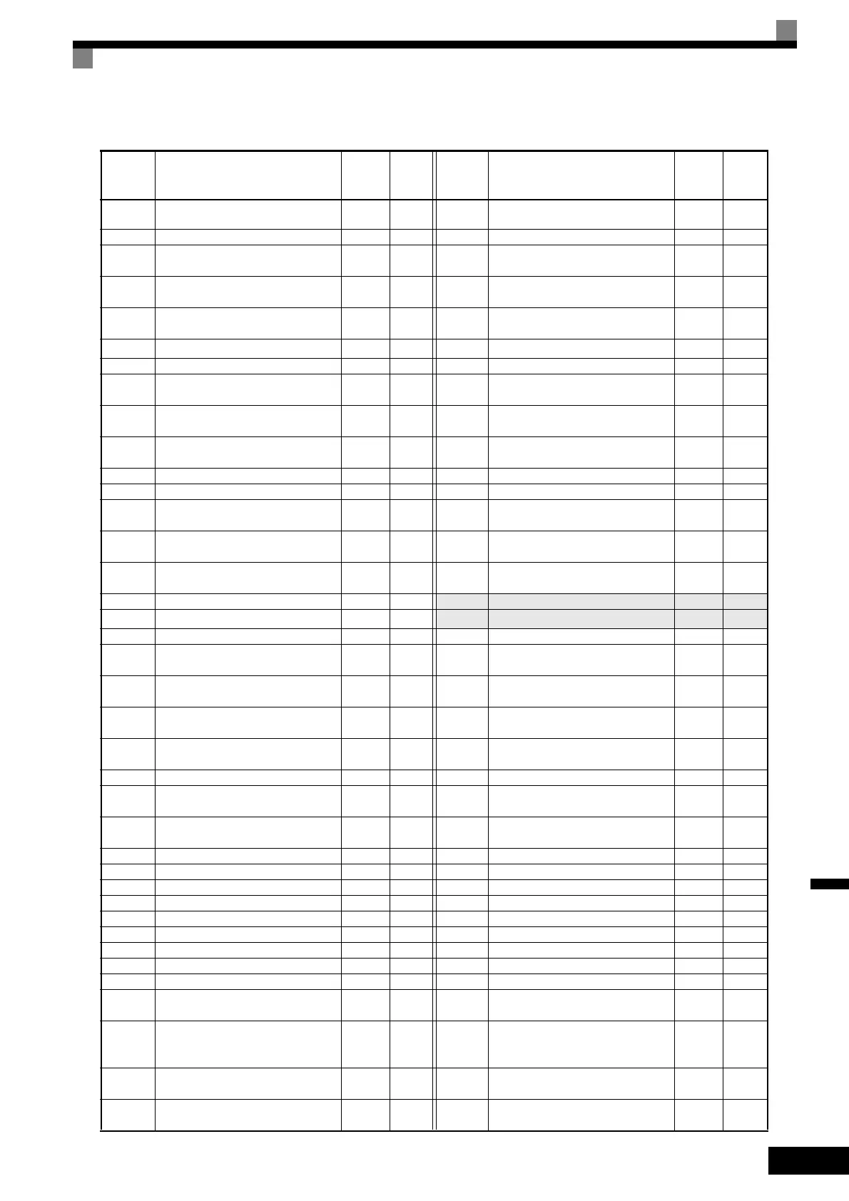
Table 10.2 User Constants (Continued)
No. Name
Fac-
tory
Setting
Set-
ting
No. Name
Fac-
tory
Setting
Set-
ting

 Loading...


