Installing and Wiring Option Boards
2-33
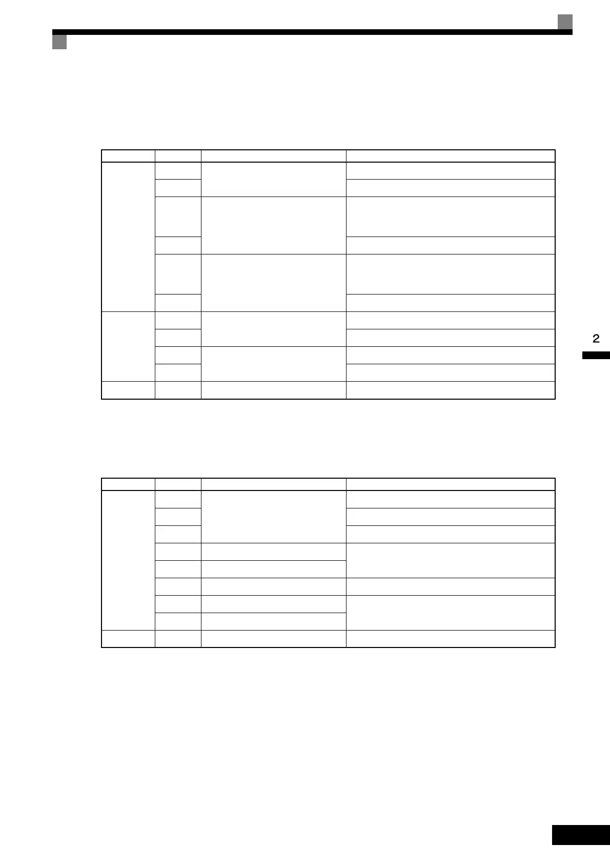
PG-B2
The terminal specifications for the PG-B2 are given in the following table.
PG-D2
The terminal specifications for the PG-D2 are given in the following table.
* 5 VDC and 12 VDC cannot be used at the same time.
Table 2.16 PG-B2 Terminal Specifications
Terminal No. Contents Specifications
TA1
1
Power supply for pulse generator
12 VDC (±5%), 200 mA max.
2 0 VDC (GND for power supply)
3
A-phase pulse input terminal
H: +8 to 12 V
L: +1 V max.
(Maximum response frequency: 30 kHz)
4 Pulse input common
5
B-phase pulse input terminal
H: +8 to 12 V
L: +1 V max.
(Maximum response frequency: 30 kHz)
6 Pulse input common
TA2
1
A-phase monitor output terminal
Open collector output, 24 VDC, 30 mA max.
2 A-phase monitor output common
3
B-phase monitor output terminal
Open collector output, 24 VDC, 30 mA max.
4 B-phase monitor output common
TA3 (E) Shield connection terminal -
Table 2.17 PG-D2 Terminal Specifications
Terminal No. Contents Specifications
TA1
1
Power supply for pulse generator
12 VDC (±5%), 200 mA max.*
2 0 VDC (GND for power supply)
3 5 VDC (±5%), 200 mA max.*
4 Pulse input + terminal
Line driver input (RS-422 level input)
Maximum response frequency: 300 kHz
5 Pulse input - terminal
6 Common terminal -
7 Pulse monitor output + terminal
Line driver output (RS-422 level output)
8 Pulse monitor output - terminal
TA2 (E) Shield connection terminal -

 Loading...


