Installing and Wiring Option Boards
2-35
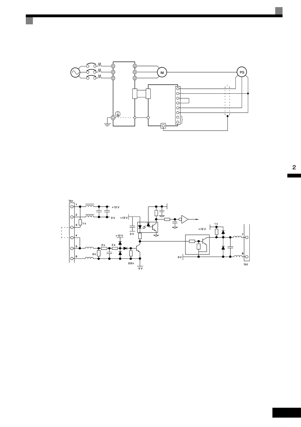
• Shielded twisted-pair wires must be used for signal lines.
• Do not use the pulse generator's power supply for anything other than the pulse generator (encoder).
Using it for another purpose can cause malfunctions due to noise.
• The length of the pulse generator's wiring must not be more than 100 meters.
Fig 2.23 Wiring an Open-collector Input
Fig 2.24 I/O Circuit Configuration of the PG-A2
Three-phase,
200 VAC (400 VAC) Inverter
+12 V power supply
0 V power supply
Open collector output (A/B phase)
Pulse 0 V
Pulse monitor output
R/L1
V/T2
W/T3
U/T1
V/T2
W/T3
4CN
4CN
E
E
1
2
3
4
5
6
7
8
TA1
TA2 (E)
PC-A2
PG power
supply
+12 V
Short for
open-col-
lector
input
Pulse
input
Pulse input
Pulse
monitor
output

 Loading...


