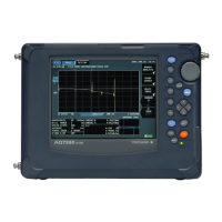
9
8
7
6
2 RD (received data): Data received from the PC.
Signal direction....input
3 SD (send data): Data sent to the PC.
Signal direction....output
5 SG (signal ground): Ground for the signal.
7 RS (request to send): Handshaking method when receiving data from the PC.
Signal direction....output
8 CS (clear to send): Handshaking method when sending data to the PC.
Signal direction....input
* Pins 1, 4, 6, and 9 are not used.
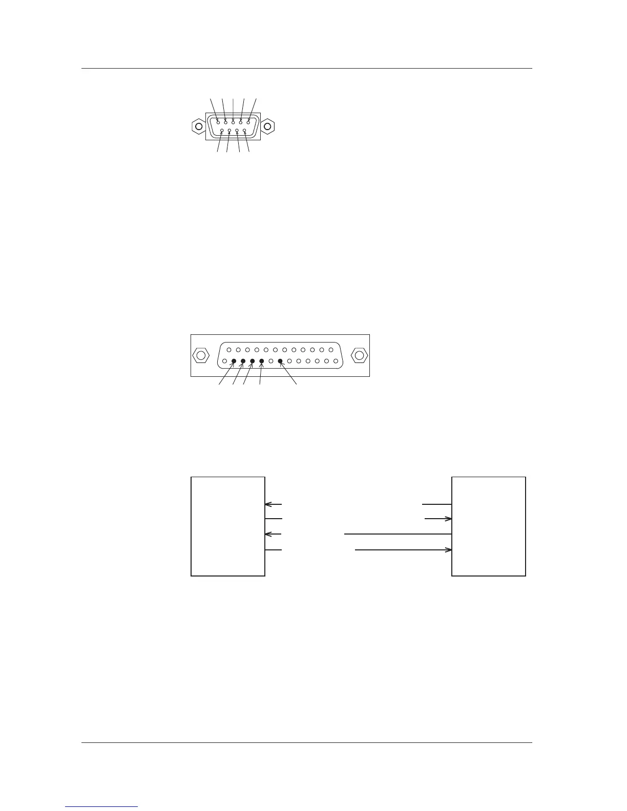
9-Pin to 25-pin Adapter and Signal Names
5 8 7 2 3
Numbers in parentheses are the pin numbers of the 25-pin connector.
Signal Direction
The directions of signals used by the instrument's serial interface are shown in the figure
below.
PC AQ6370
RS [Request to send ... Receive OK]
SD [Send data]
RD [Receive data]
2
3
8
7
CS [Clear to send ... Preparation OK]
4.1 Connecting via the Serial (RS-232C) Interface

 Loading...