6.2 Status Byte Registers
Structure
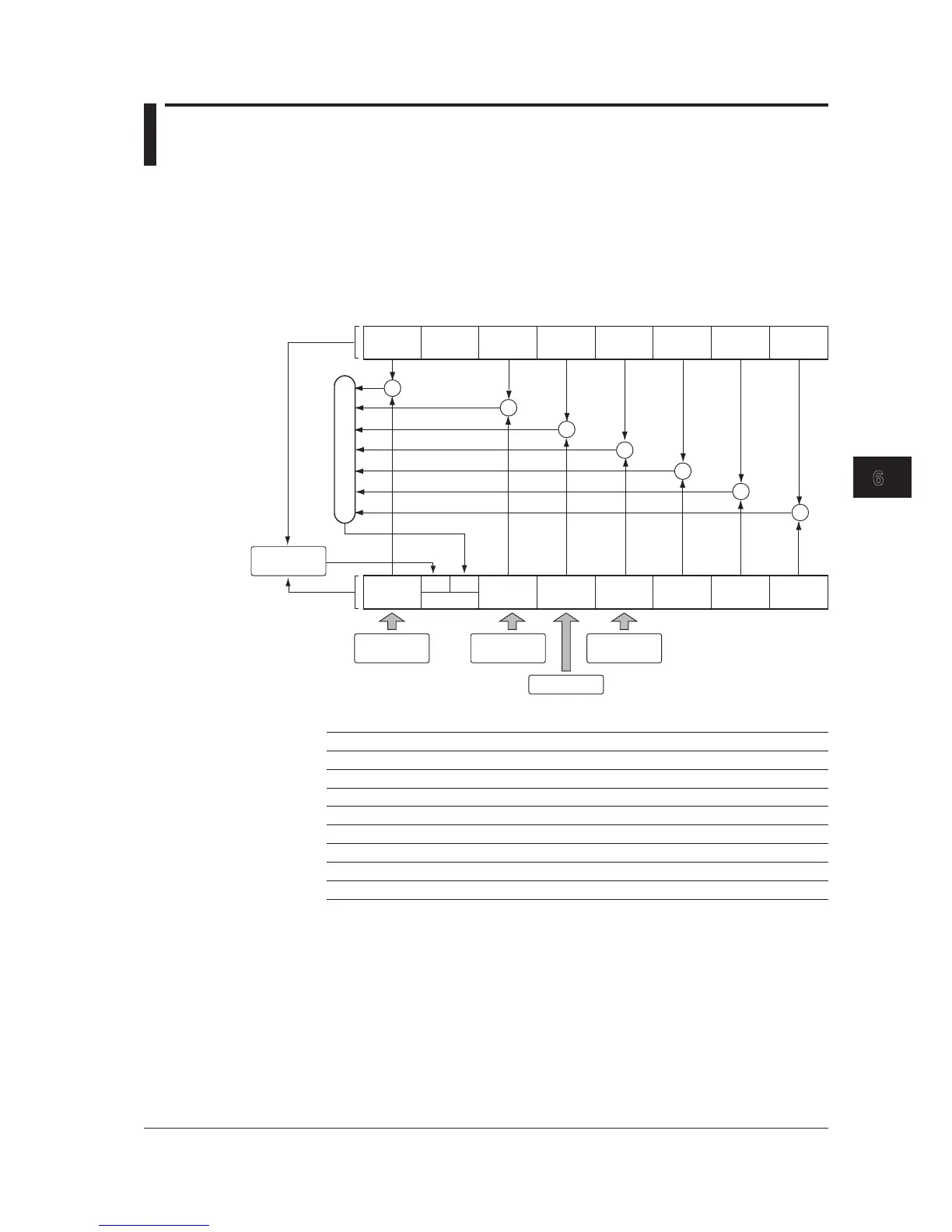
The structure of the status byte registers is shown below. The contents and actions of
these registers comply with the IEEE 488.2 standards.
Also, the AQ6370C/AQ6370D/AQ6373/AQ6373B/AQ6375/AQ6375B also provides the
extended OPS and QUS bits to the status byte register.
Operation Event
Status
bit 7
OPS
bit 6
bit 5
ESB
bit 4
MAV
bit 3
QUS
bit 2 bit 1 bit 0
Output buffer
RQS
MSS
Standard Event
Status
Questionable
Event Status
bit 7 bit 6 bit 5 bit 4
bit 3
bit 2 bit 1 bit 0
Generates
service request
During serial
poll
When *STB? sent
OR
&
&
&
&
&
&
&
Status Byte Register Contents
Bit Event Name Description Decimal Value
Bit 7 OPS Summary bit of operation status 128
Bit 6 RQS, MSS “1” if there is more than one service request 64
Bit 5 ESB Summary bit of standard event status register 32
Bit 4 MAV “1” if the output buffer contains data 16
Bit 3 QUS Summary bit of questionable status 8
Bit 2 None Not used (always 0) 0
Bit 1 None Not used (always 0) 0
Bit 0 None Not used (always 0) 0

 Loading...