6.3 Standard Event Status Registers
Structure
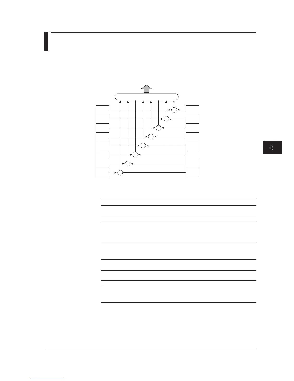
The structure of the standard event status registers is shown below. The contents and
actions of the registers comply with the IEEE 488.2 standards.
PON
bit 7
bit 6
CME
bit 5
EXE
bit 4
DDE
bit 3
QYE
bit 2
bit 1
OPC
bit 0
OR
&
Power on
not used
Command error
Execution error
Contents of the Standard Event Status Registers
Bit Event Name Description Decimal Value
Bit 7 PON (Power ON) Power is turned ON. 128
Set to “1” at startup.
Bit 6 None Not used (always 0) 0
Bit 5 CME A syntax error or unrecognizable command is 32
(command error) detected. GET is encountered between the 1st byte
of a program message and the program message
terminator.
Bit 4 EXE (Execution error) Program data following the program header is 16
out of the effective range. Receipt of a program
message contradictory to device state.
Bit 3 DDE Error caused by an event other than CME, EXE, 8
(Device-specific error) or QYE.
Bit 2 QYE (Query error) Access to an output queue was made with no 4
output existing. Output queue data was lost.
Bit 1 None Not used (always 0) 0
Bit 0 OPC Completion of command action: 1
(operation complete) Enabled only when *OPC is received
Disabled if *OPC? is received

 Loading...