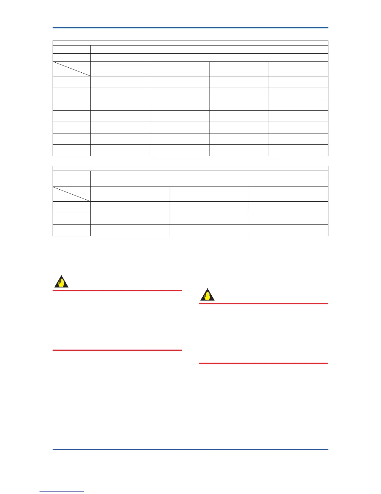
Table 3.3.6 Wafer Type Tightening Torque Values for Metal Piping and Permeable Fluids
Tightening torque values for PFA lining type (N-m / {kgf-cm} / [in-lbf])
Gasket types within
owtube
No gasket (standard)
Gasket types for user’s
ange
PTFE-sheathed non-asbestos gasket (optional codes BCF and BSF), or the equivalent in hardness
Flange
ratings
Size
mm (inch)
JIS 10K
ANSI Class 150
DIN PN10
JIS 20K
ANSI Class 300
DIN PN16
DIN PN40 JPI Class 150
2.5 (0.1)
10.8 to 12.4
{110.1 to 126.4}
[95.59 to 109.7]
10.8 to 12.4
{110.1 to 126.4}
[95.59 to 109.7]
11.1 to 12.4
{113.2 to 126.4}
[98.24 to 109.7]
11.8 to 12.1
{120.6 to 123.7}
[104.6 to 107.3]
5 (0.2)
10.8 to 12.4
{110.1 to 126.4}
[95.59 to 109.7]
10.8 to 12.4
{110.1 to 126.4}
[95.59 to 109.7]
11.1 to 12.4
{113.2 to 126.4}
[98.24 to 109.7]
11.8 to 12.1
{120.6 to 123.7}
[104.6 to 107.3]
10 (0.4)
10.8 to 12.4
{110.1 to 126.4}
[95.59 to 109.7]
10.8 to 12.4
{110.1 to 126.4}
[95.59 to 109.7]
11.1 to 12.4
{113.2 to 126.4}
[98.24 to 109.7]
11.8 to 12.1
{120.6 to 123.7}
[104.6 to 107.3]
15 (0.5)
10.8 to 12.4
{110.1 to 126.4}
[95.59 to 109.7]
10.8 to 12.4
{110.1 to 126.4}
[95.59 to 109.7]
11.1 to 12.4
{113.2 to 126.4}
[98.24 to 109.7]
11.8 to 12.1
{120.6 to 123.7}
[104.6 to 107.3]
25 (1.0)
34.9 to 40.1
{355.9 to 408.9}
[308.9 to 354.9]
35.2 to 40.1
{358.9 to 408.9}
[311.5 to 354.9]
32.3 to 37.1
{329.4 to 378.3}
[285.9 to 328.4]
29.2 to 29.9
{297.6 to 305.5}
[258.1 to 265.0]
32 (1.25)
38.8 to 44.6
{395.6 to 454.8}
[343.4 to 394.7]
39.2 to 44.6
{399.7 to 454.8}
[346.9 to 394.7]
40.6 to 46.7
{414.0 to 476.2}
[359.3 to 413.3]
―
40 (1.5)
53.5 to 61.5
{545.5 to 627.1}
[473.5 to 544.3]
54.2 to 61.5
{552.7 to 627.1}
[479.7 to 544.3]
56.4 to 61.5
{575.1 to 627.1}
[499.2 to 544.3]
44.6 to 45.8
{455.0 to 467.3}
[394.7 to 405.3]
Tightening torque values for Ceramics lining type (N-m / {kgf-cm} / [in-lbf])
Gasket types within
owtube
Fluororesinwithceramicllers(Valqua#7020)gasket(standard),oruororesinwithcarbongasket(optionalcodeGF)
Gasket types for user’s
ange
PTFE-sheathed non-asbestos gasket (optional codes BCF and BSF), or the equivalent in hardness
Flange
ratings
Size
mm (inch)
JIS 10K
ANSI Class 150
DIN PN10
JIS 20K
ANSI Class 300
DIN PN16
DIN PN40
15 (0.5)
8.1 to 13.1
{82.6 to 133.6}
[71.7 to 115.9]
8.1 to 13.1
{82.6 to 133.6}
[71.7 to 115.9]
7.9 to 13.1
{80.6 to 133.6}
[69.9 to 115.9]
25 (1.0)
22.5 to 29.0
{229.4 to 295.7}
[199.1 to 256.7]
22.7 to 29.0
{231.5 to 295.7}
[200.9 to 256.7]
17.4 to 29.0
{177.4 to 295.7}
[154.0 to 256.7]
40 (1.5)
40.6 to 53.8
{414.0 to 548.6}
[359.3 to 476.2]
49.3 to 67.7
{502.7 to 690.3}
[436.3 to 599.2]
40.6 to 67.7
{414.0 to 690.3}
[359.3 to 599.2]
3.3.3 Nominal Diameter 50 mm (2.0 in.) to
300 mm (12.0 in.), Wafer Type
IMPORTANT
Useboltsandnutsincompliancewiththeange
ratings. When stud-type through-bolts are used, be
sure the outside diameter of the shank is smaller than
that of the thread ridge. Be sure to choose a gasket
with inner and outer diameters that does not protrude
inside the piping (refer to Table 3.3.16). If the inner
diameter of the gasket is too large, or outer diameter
ofthegasketistoosmall,uidleakagemayresult.
(1) Mounting Direction
Mounttheowmetersothattheowdirectionoftheuid
to be measured is in line with the direction of the arrow
markontheowmeter.
IMPORTANT
If it is impossible to match the direction of the arrow
mark, the direction of the electrical connection can
be changed. Refer to the applicable user’s manuals
which can be downloaded from our website.
Incasetheuidbeingmeasuredowsagainstthe
arrowdirection,changethevaluefrom“Forward”to
“Reverse”attheparameter[J20:FlowDirection]
(refer to Chapter 8).
 Loading...

