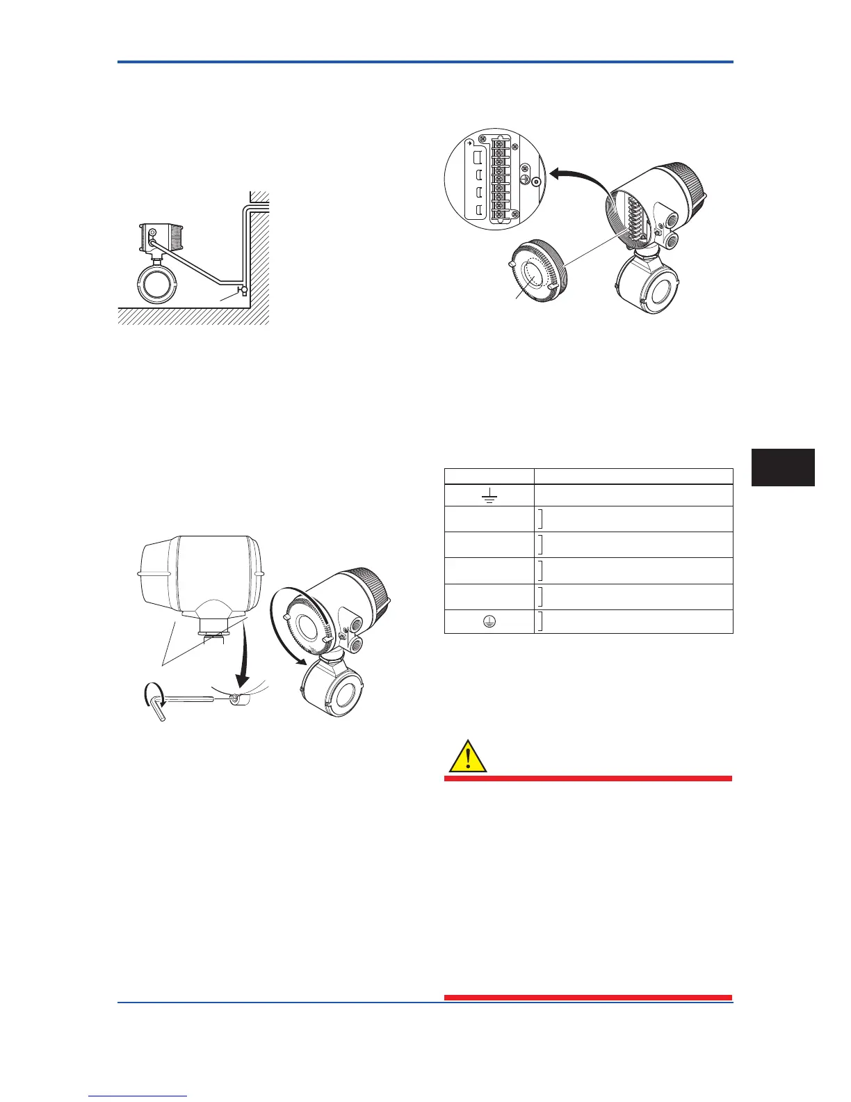
(3) Conduit Wiring
When wiring the conduits, pass the conduit through the
wiring connection port, and utilize the waterproof gland to
preventwaterfromowingin.Placetheconduitpipeon
an angle as shown in Figure 4.1.4.
Install a drain valve at the low end of the vertical pipe, and
open the valve regularly.
Drain valve
Figure 4.1.4 Conduit Wiring
4.1.4 Wiring Connections for Integral
Flowmeter
(1) Removing Cover
Loosen cover locking screw 2 clockwise using a
hexagonal wrench (nominal size 3) to unlock the cover.
(Upon shipment from the manufacturing plant, the cover
isunlocked.)Holdtheowmeterwithyourhandand
remove the cover by turning it in the direction of the arrow
as shown below.
Figure4.1.6 TerminalCongurationforIntegralFlowmeter
The description of the terminal symbols is shown in Table
4.1.1.
For F
OUNDATIONeldbusprotocol,refertoIM01E20F02-
01E.
For PROFIBUS PA protocol, refer to IM 01E20F12-01E.
Table 4.1.1 Terminal Symbols for Integral Flowmeter
Terminal Symbols Description
Functional grounding
N/–
L/+
Power supply
I+
I–
Current output 4 to 20mA DC
DO+
DO–
Pulse output/Alarm output/ Status output
DIO+
DIO–
Alarm output/Status output Status input
Protective grounding (Outside of the terminal)
(3) Precautions for Wiring of Power Supply
Cables
When connecting to the power supply, observe the points
below. Failure to comply with these warnings may result
in an electric shock or damage to the instrument.
WARNING
• Ensure that the power supply is OFF in order to
prevent electric shocks.
• Ensure the protective grounding terminal is
grounded before turning the power on.
• Use insulating sleeve crimp terminals (for 4-mm
screws) for the power supply wiring and protective
grounding wiring.
• Install an external switch or circuit breaker as a
means to turn the power off (capacitance; 15A,
conforming to IEC60947-1 and IEC60947-3).
Locate this switch either near the instrument or
inotherplacesfacilitatingeasyoperation.Afxa
“PowerOffEquipment”labeltothisexternalswitch
or circuit breaker.
 Loading...

