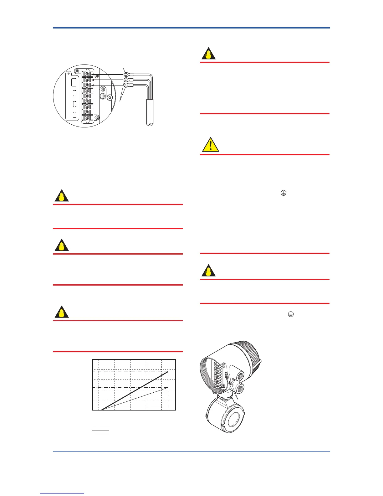
Power supply
cable
Figure 4.1.7 Electric Cable Wiring for Integral Flowmeter
(4) DC Power Connection
When using DC power as the power supply for the
converter, give attention to the following points.
1) Connecting Power Supply
IMPORTANT
Do not connect power supply with reversed polarities.
L/+ terminal: connect +
N/– terminal: connect –
IMPORTANT
Do not connect power supply with 100 to 240 V
AC or 100 to 120 V DC in the case of a 24 V
power supply version (power supply code 2).
It will give a damage to the converter.
2) Required Power Supply Voltages
IMPORTANT
Whenusinga24Vpowersupply,thespecicationfor
the supply voltage is 24 V (–15% to +20%), but the input
voltage of the converter drops due to cable resistance
therefore it must be used within the following ranges.
Usable range E (V)
Cable cross section area: 1.25 mm
2
Cable cross section area: 2 mm
2
length m(ft)
0
20.4 22 24 26 28.8
200 ( 660)
796 (2610)
796 (2610)
796 (2610)
Figure 4.1.8 Supply Voltage and Cable Length for Integral
Flowmeter
3) Setting Power Supply Frequency
IMPORTANT
Set the local commercial power frequency in order to
eliminate the effect of induction noise from the power
supply.
Referto“ParameterDescription”intheuser’smanual
of the AXF Integral Flowmeter [Software Edition] (IM
01E20C02-01E).
Parameter No.: J30 and J31
(5) Grounding
CAUTION
Be sure to connect the protective grounding of the
AXFintegralowmeterwithacableof2mm
2
or larger
cross section in order to avoid electrical shock to the
operators and maintenance engineers and to prevent
theinuenceofexternalnoise.
Connect the grounding wire to the
mark.
The grounding should satisfy Class D requirements
(groundingresistance,100Ωorless).
In case of TIIS Flameproof type, the grounding should
satisfy Class C requirements (grounding resistance,
10Ωorless)orclassArequirements(grounding
resistance,10Ωorless).
For explosion proof type except TIIS, follow the domestic
electrical requirements as regulated in each country.
IMPORTANT
When optional code A (lightning protector) is selected,
the ground should satisfy Class C requirements
(groundingresistance,10Ωorless).
• The protective grounding terminals
are located on
the inside and outside of the terminal area.
Either terminal may be used.
•
Use 600 V vinyl insulation wires as the grounding wires.
 Loading...

