IMPORTANT
Improper grounding can have an adverse effect on
theowmeasurement.Ensurethattheinstrumentis
properly grounded.
Theelectromotiveforceofthemagneticowmeter
is minute and it is easily affected by noise, and the
reference electric potential is the same as that of the
measuringuid.Therefore,thereferenceelectric
potential(terminalpotential)oftheowtubeandconverter
alsoneedtobethesameasthatofthemeasuringuid.
Moreover, the potential must be the same as the ground.
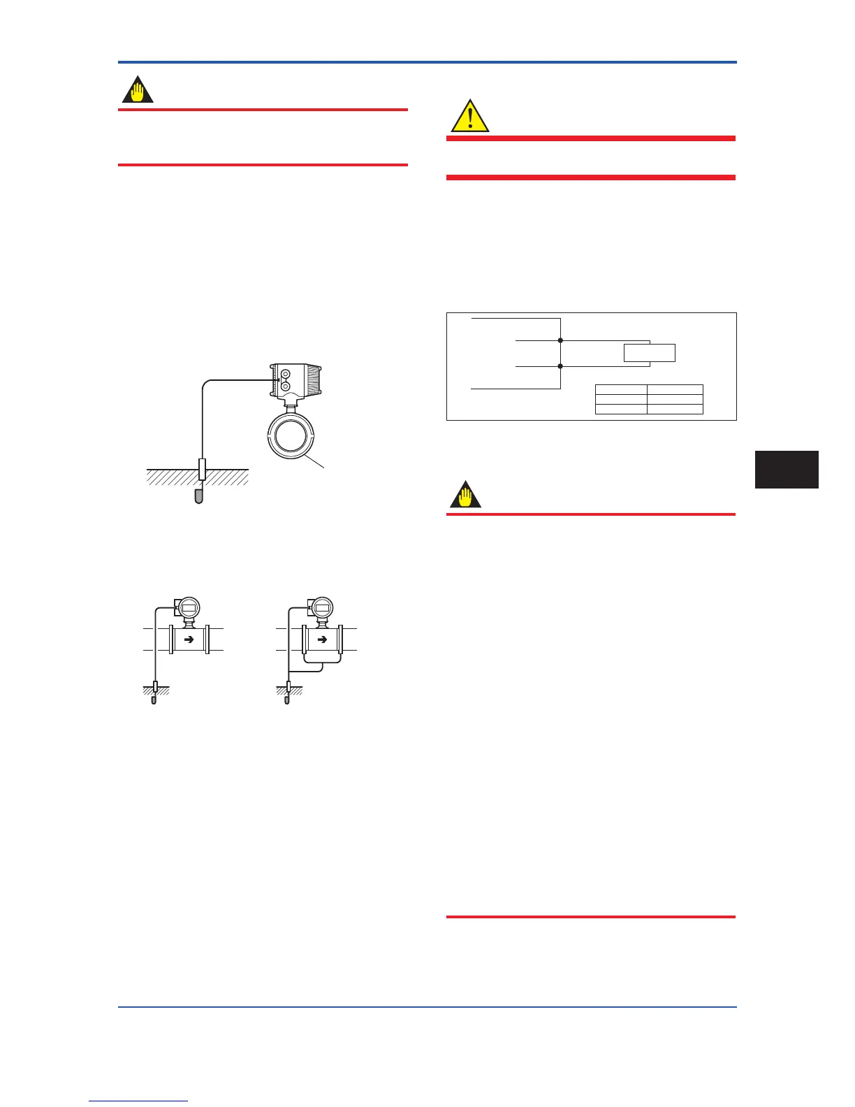
Themagneticowmeterisequippedwithangrounding
ring that makes a connection with the charge of the
measureduidforgroundingandprotectsthelining.Be
suretogroundtheowmeteraccordingtoFigure4.1.10.
(Available only for metal piping)
Figure 4.1.10 Grounding for Integral Flowmeter
(6) Connecting to External Instruments
WARNING
Before wiring with external instruments, be sure to turn
offthemagneticowmeterandanyexternalinstruments.
ConnecttheAXFintegralowmeterterminaltoexternal
instruments, giving attention to the following points.
For F
OUNDATIONeldbusprotocol,refertoIM01E20F02-
01E.
For PROFIBUS PA protocol, refer to IM 01E20F12-01E.
4 to 20 mA DC Current Output
Resistive load max. 750 Ω
Receiver
Instrument
AXF integral flowmeter
l+
l-
F0411.ai
Communication
Resistive load
BRAIN
HART
250 to 450 Ω
250 to 600 Ω
Figure 4.1.11 4 to 20 mA DC Output Connection
Pulse Output
IMPORTANT
• As this is a transistor contact (insulated type), give
attention to proper voltage and polarity when wiring.
• Do not apply a voltage larger than 30V DC or
a current larger than 0.2A in order to prevent
damage to the instrument.
• Wheninputlterconstantoftheelectroniccounter
is large in relation to the pulse width, the signal will
decrease and the count will not be accurate.
• If the input impedance of the electronic counter is
large, an induction noise from the power supply
may result in inaccurate counts. Use a shield cable
orsufcientlyreducetheinputimpedanceofthe
electroniccounterwithinthemagneticowmeter
pulseoutputspecicationrange.
• The active pulse output (Optional code EM) cannot
be used in conjunction with the standard pulse
output.
•
When the active pulse output (Optional code EM) is
selected, do not be short-circuit between the DO+
and DO– terminals to avoid damaging the instrument.
• When the active pulse output (Optional code EM)
is selected, the range of pulse rate must be set to 2
pps maximum.
• To avoid communication (BRAIN/ HART) failure, it
is recommended to use the shield cable.
 Loading...

