4.2.4 Wiring Connections for Remote
Flowtube
WARNING
Before wiring, be sure that the power supply for
AXFA11 or AXFA14 converter has been turned off to
prevent an electrical shock.
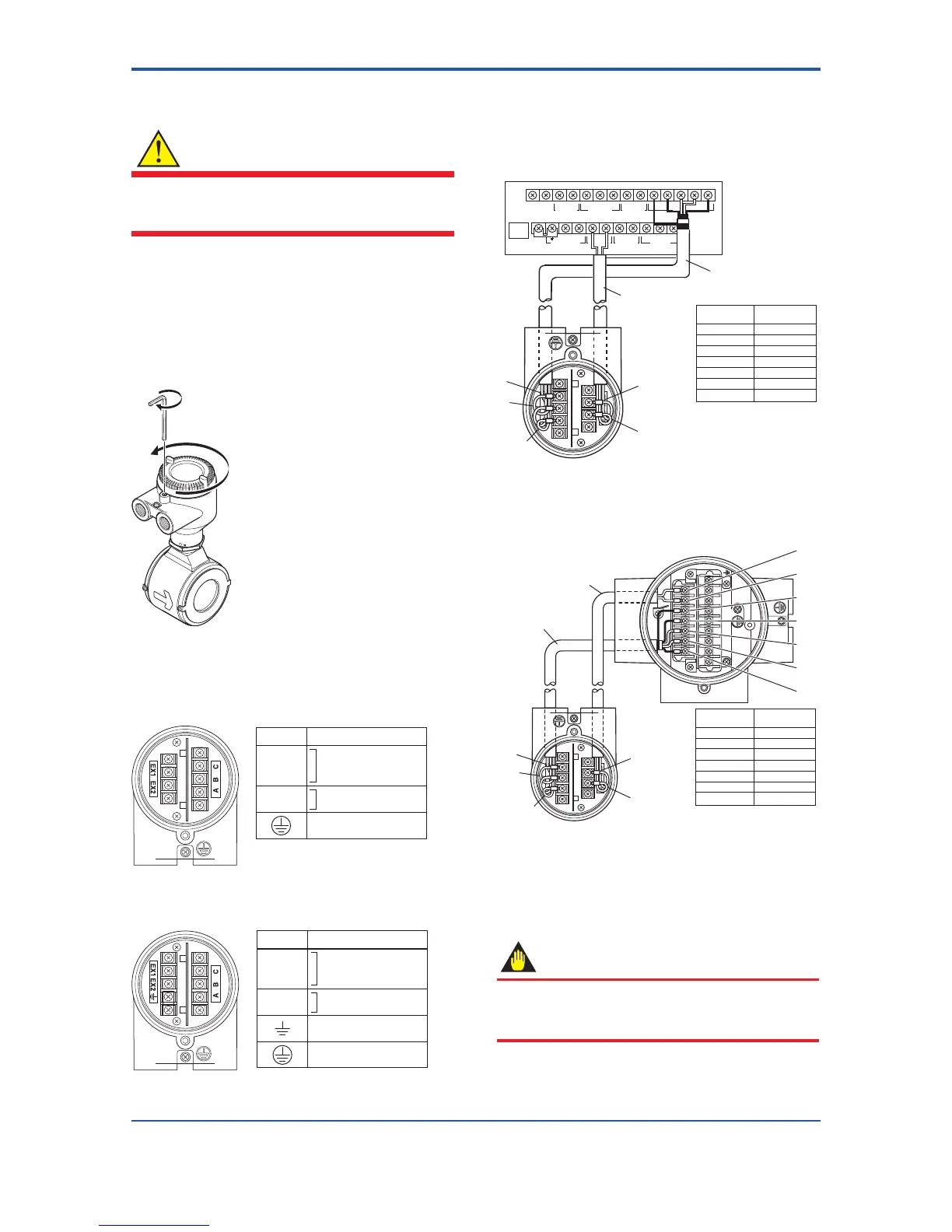
(1) Removing Cover
Loosen the cover locking screw clockwise using a
hexagonal wrench (nominal size 3) to unlock the cover.
(Upon shipment from the manufacturing plant, the cover
isunlocked.)Holdtheowtubewithyourhandand
remove the cover by turning it in the direction of the arrow
as shown below.
Figure 4.2.8 Removing the Terminal Box Cover for Remote
Flowtube
(2) TerminalConguration
When the cover is removed, the connection terminals
Symbols
A
B
C
EX1
EX2
Flow signal output
Excitation current input
Protective grounding
(Outside of the terminal)
Description
Figure4.2.9 TerminalCongurationforRemoteFlowtube
(General-Purpose Use, Submersible Type,
Sanitary Type)
A
B
C
EX1
EX2
Terminal
Symbols
Description
Flow signal output
Excitation current input
Functional grounding
(Only for explosion proof type)
Protective grounding
(Oitside of the terminal)
Figure4.2.10 TerminalCongurationforRemoteFlowtube
(Explosion proof Type)
(3) Wiring the Remote Flowtube (General-
Purpose Use, Submersible Type, Sanitary
Type) with Converters
1) Connection with the AXFA11 converter
Connectwiringasshowninthegurebelow.
I+ I–
CURRENT OUT
AL+ AL– C SA A B SB
ALARM OUT
N/– L/+
POWER SUPPLY
EX2EX1
EXCIT ATION
P– SI1+ SI2+ COMP+
PULSE OUT STATUS IN
SIGNAL
SO1+ COMSO2+
STATUS OUT
FUSE
2.5A 250V
Remote flowtube
AXFC dedicated
signal cable
Converter
Remote
flowtube
SA
A
B
SB
C
EX1
EX2
Taping*
A
B
Taping*
C
EX1
EX2
* Individually tape and insulate
the shields corresponding to
SA and SB on the remote
flowtube side.
EX2
EX1
B
C
Excitation cable
Figure 4.2.11 Wiring Diagram
2) Connection with the AXFA14 converter
Connectwiringasshowninthegurebelow.
AXFC dedicated
signal cable
EX2
EX1
A
B
C
Excitation cable
C
SA
A
B
SB
F0428.ai
Converter
Remote
flowtube
SA
A
B
SB
C
EX1
EX2
Taping*
A
B
Taping*
C
EX1
EX2
* Individually tape and insulate
the shields corresponding to
SA and SB on the remote
flowtube side.
Remote flowtube
Figure 4.2.12 Wiring Diagram
(4) Wiring the Remote Flowtube (Explosion
Proof Type) with Converters
IMPORTANT
IncaseofATEX,IECExorTIIScertiedAXFremote
owtube,itisonlyapprovedtobecombinedwith
AXFA14 converter.
 Loading...

