F0460.ai
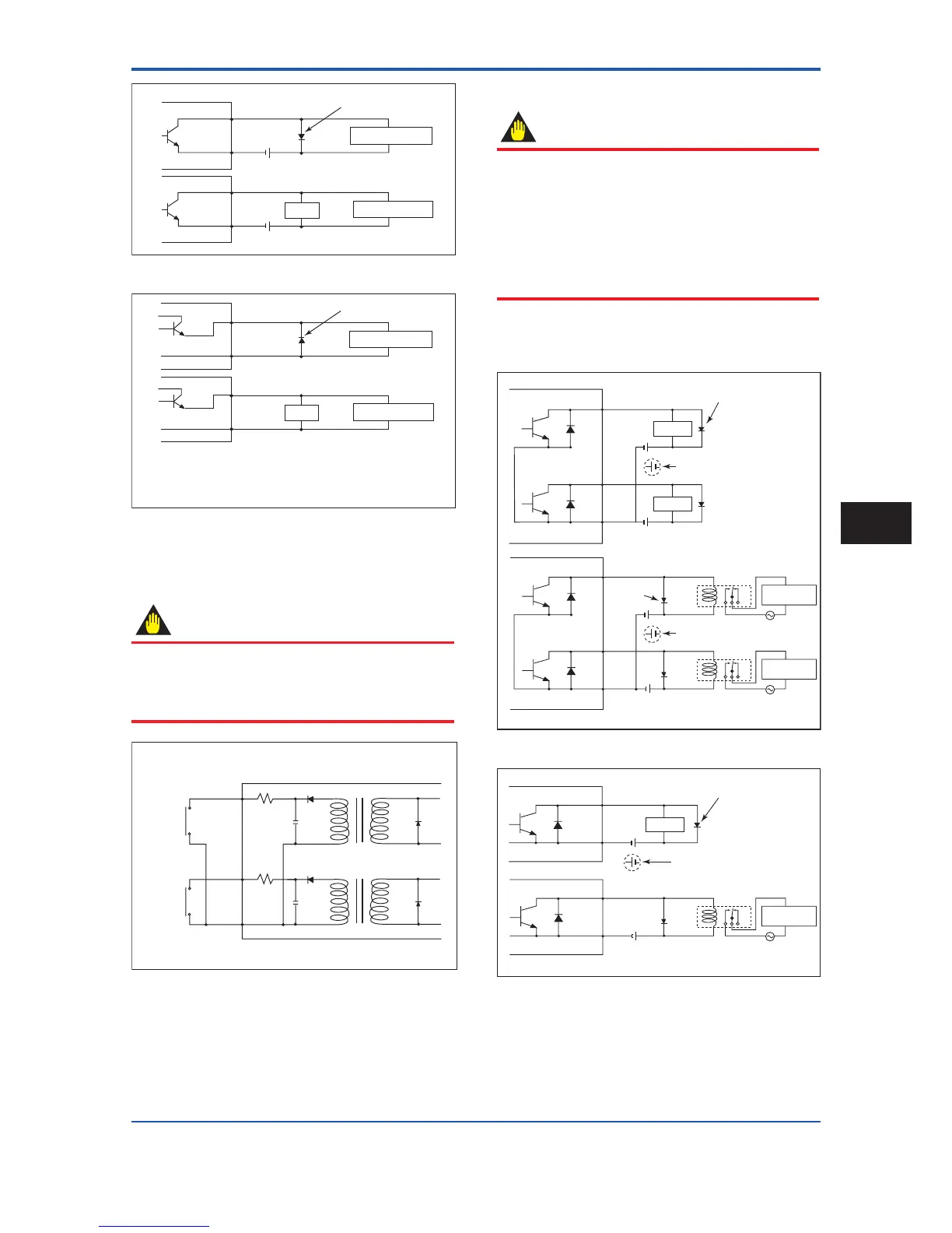
Mechanical Counter
Electronic Counter
Load
Protective diode
30V DC, 0.2A. max
PULSE OUT
PULSE OUT
AXFA11
AXFA11
P+
P-
P+
P-
Figure 4.4.13 Pulse Output Connection
F0461.ai
Protective diode
PULSE OUT
AXFA11
AXFA11
P+
P-
P+
P-
Output voltage: 24 V DC ±20%
Current: 150 mA or less
Pulse rate: 0.0001 to 2 pps
Pulse width: 20, 33, 50, 100 ms
Mechanical Counter
Electronic Counter
Load
PULSE OUT
Figure 4.4.14 Active Pulse Output Connection
(Optional code EM)
Status Input
IMPORTANT
Status inputs are designed for use with no-voltage
(dry) contacts. Be careful not to connect the status to
any signal source carrying voltage.
Applying voltage may damage the input circuit.
AXFA11
SI1
+
SI2
+
COM
F0462.ai
No-voltage status input
Closed: Less than 200 Ω
Open: More than 100 kΩ
Figure 4.4.15 Status Input Connection
Status Output / Alarm Output
IMPORTANT
Since this is an isolated transistor output, be careful of
voltage and polarity when wiring.
Do not apply a voltage larger than 30V DC or a current
larger than 0.2A in order to prevent damage to the
instrument.
This output cannot switch an AC load. To switch an AC
load, an intermediate relay must be inserted as shown
in Figure 4.4.16 or Figure 4.4.17.
* The alarm output operates from closed (normal) to open
(alarm occurrence) by factory default setting. Changes
can be made via the parameter settings.
F0463.ai
Load
Load
Protective diode
Protective
diode
External power supply
30V DC, 0.2A. max
AXFA11
External power supply
30V DC, 0.2A. max
AXFA11
This connection is not possible.
This connection is not possible.
SO1
+
SO2
+
COM
SO1
+
SO2
+
COM
Electromagnetic
valve
Electromagnetic
valve
AC power supply
Relay
Figure 4.4.16 Status Output Connection
F0464.ai
Load
Protective diode
External power supply
30V DC, 0.2A. max
AXFA11
AXFA11
This connection is not possible.
AL
+
AL
-
AL
+
AL
-
Electromagnetic
valve
AC power supply
Relay
Figure 4.4.17 Alarm Output Connection
 Loading...

