(5) Grounding
CAUTION
Be sure to connect the protective grounding of the
AXFA11 with a cable of 2mm
2
or larger cross section
in order to avoid electrical shock to the operators and
maintenanceengineersandtopreventtheinuence
of external noise. Connect the grounding wire to the
mark
(100Ωorless).
IMPORTANT
When optional code A (lightning protector) is selected,
the ground should satisfy Class C requirements
(groundingresistance,10Ωorless).
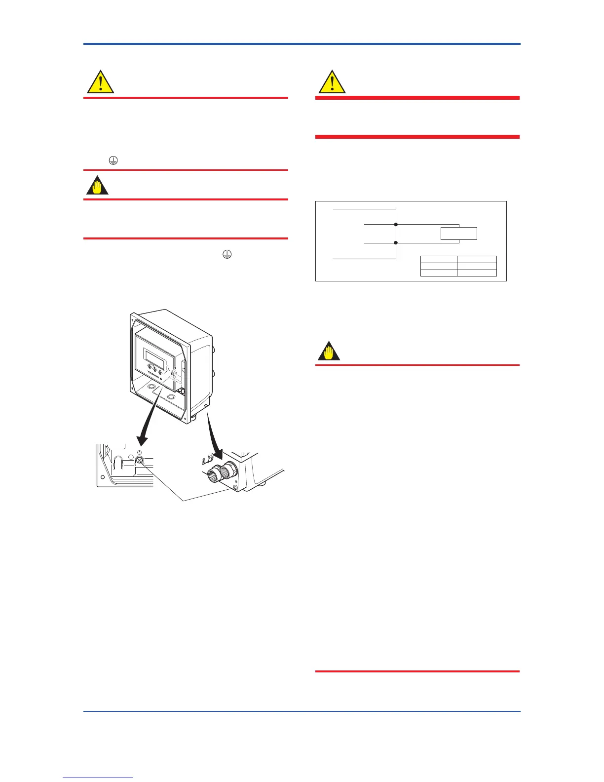
• The protective grounding terminals
are located on
the inside and outside of the terminal area.
Either terminal may be used.
• Use 600 V vinyl insulation wires as the grounding
wires.
Protective grounding terminals
Figure 4.4.11 Protective Grounding Terminal Location for
AXFA11 Remote Converter
(6) Connecting to External Instruments
WARNING
Before wiring with external instrument, be sure to turn
off the power supply for AXFA11 converter and any
external instruments.
Connect the AXFA11 terminal to external instruments,
giving attention to the following points.
4 to 20 mA DC Current Output
Resistive load max. 1 kΩ
Receiver
Instrument
AXFA11
l+
l-
Communication
Resistive load
BRAIN
HART
250 to 450 Ω
250 to 600 Ω
Figure 4.4.12 4 to 20 mA DC Output Connection
Pulse Output
IMPORTANT
• As this is a transistor contact (insulated type),
give attention to proper voltage and polarity when
wiring.
• Do not apply a voltage larger than 30V DC or
a current larger than 0.2A in order to prevent
damage to the instrument.
• Wheninputlterconstantoftheelectroniccounter
is large in relation to the pulse width, the signal will
decrease and the count will not be accurate.
• If the input impedance of the electronic counter is
large, an induction noise from the power supply
may result in inaccurate counts. Use a shield
cableorsufcientlyreducetheinputimpedanceof
the electronic counter within the electromagnetic
owmeterpulseoutputspecicationrange.
• The active pulse output (Optional code EM) cannot
be used in conjunction with the standard pulse
output.
• When the active pulse output (Optional code
EM) is selected, do not be short-circuit between
the P+ and P– terminals to avoid damaging the
instrument.
• When the active pulse output (Optional code EM)
is selected, the range of pulse rate must be set to 2
pps maximum.
• To avoid communication (BRAIN/ HART) failure, it
is recommended to use the shield cable.
 Loading...

