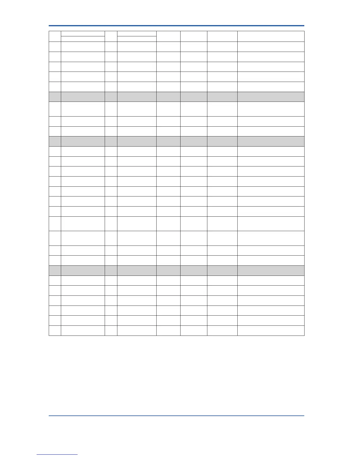
Item
Name
R/W
(*3)
Data range
Units
Position of
decimal point
Default value (*):
Indicated item
Description
Display unit (BRAIN) Display unit/BRAIN
K12 Adhesion Level2
(ADH LEVEL2)
W 0.00 to 100.00 MΩ 2 0.50 Sets the resistance value for adhesion
Level 2 to the electorode.
K13 Adhesion Level3
(ADH LEVEL3)
W 0.00 to 100.00 MΩ 2 1.00 Sets the resistance value for adhesion
Level 3 to the electorode.
K14 Adhesion Level4
(ADH LEVEL4)
W 0.00 to 100.00 MΩ 2 3.00 Sets the resistance value for adhesion
Level 4 to the electorode.
K15 Adh Measure Value
(ADH MEAS VAL)
R — MΩ 2 Displays the resistance value for
adhesion to the electrode.
K60 —
(SELF CHECK)
R Good
Error
See Chapter 7.
M00 Adjustment
(ADJUSTMENT)
M10 Auto Zero Exe
(AUTOZERO EXE)
W No Execution
Execution
No Execution Selects whether or not automatic zero
adjustment is carried out. Linked with
B50.
M11 MagowZero
(MAGFLOW ZERO)
R/W -99.999 to 99.999 3 0.000 Displays the result of the automatic zero
adjustment, or sets the zero point.
M60 —
(SELF CHECK)
R Good
Error
See Chapter 7.
N00 Test
(TEST)
N10 Test Mode
(TEST MODE)
W Normal
Test
Normal Selects whether mode will be set to
“Normal”or“Test”.
N11 Test Output Value
(TEST OUT VAL)
W -10 to 110 % 0 0 % Sets the test output value.
N20
(*1)
Test SO1
(TEST SO1)
W Open(Off)
Closed(On)
Open(Off) Selects the test condition for SO1
terminal.
N21
(*1)
Test SO2
(TEST SO2)
W Open(Off)
Closed(On)
Open(Off) Selects the test condition for SO2
terminal.
N22
(*1)
Test Alarm Out
(TEST ALM OUT)
W Open(Off)
Closed(On)
Closed(On) Selects the test condition for alarm
output terminal.
N23
(*1)
Test SI1
(TEST SI1)
R Open
Short
Displays the test condition for SI1
terminal.
N24
(*1)
Test SI2
(TEST SI2)
R Open
Short
Displays the test condition for SI2
terminal.
N30
(*2)
Test DO
(TEST DO)
W Open(Off)
Closed(On)
Pulse
Open(Off) Selects the test condition for DO
terminal.
N31
(*2)
Test DIO (O)
(TEST DIO (O))
W Input Mode
Open(Off)
Closed(On)
Input Mode Selects the test condition for DIO
terminal used for output.
N32
(*2)
Test DIO (I)
(TEST DIO (I))
R Open
Short
Displays the test condition for DIO
terminal used for input.
N60 —
(SELF CHECK)
R Good
Error
See Chapter 7.
P00 Protect
(PROTECT)
P10 Key Code
(KEY CODE)
W 0 to 9999 0 Parameter of the display restriction
P20 Write Protect
(W PROTECT)
R No
Yes
No Displays whether or not overwriting of
parameter data is prohibited.
P21 Enable Wrt Passwd
(ENABLE WRITE)
W ASCII 8 characters Sets the correct password so that write
protection function will be released.
P22 New Password
(NEW PASSWORD)
W ASCII 8 characters Sets the password for write protection
funcion
P23 Software Seal
(SOFT SEAL)
R Break
Keep
Keep DisplayswhetherornotaJoker
password was used (Break).
P60 —
(SELF CHECK)
R Good
Error
See Chapter 7.
*1: Applicable for AXFA11 Remote Converter.
*2: Applicable for AXF Integral Flowmeter and AXFA14 Remote Converter.
*3: R/W: R = Read only, W = Read and Write
 Loading...

