<3. ABOUT FIELDBUS>
3-2
IM 01F06F00-01EN
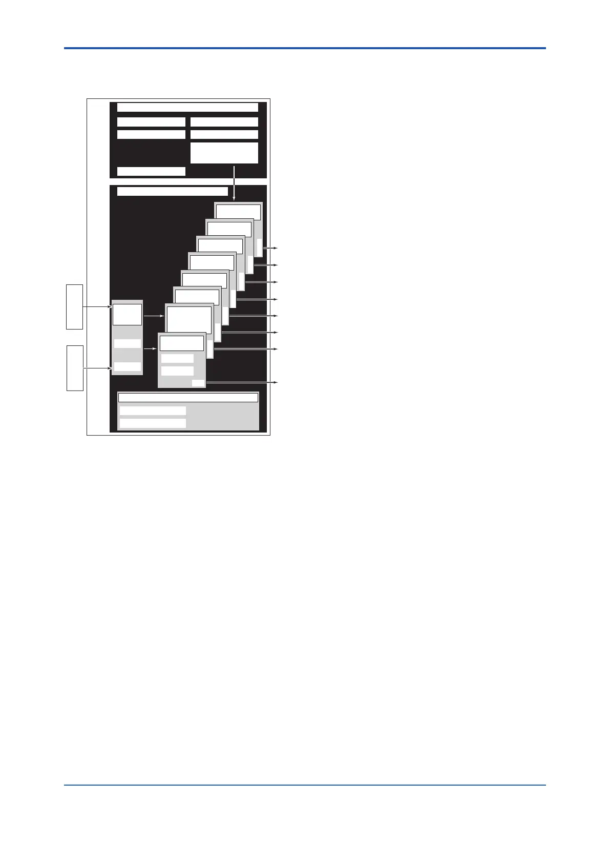
3.3 Logical Structure of Each
Block
F0301.ai
digital
YEWFLO
System/network management VFD
Function block VFD
PD tag
Sensor
input
Resource block
Block tag
Parameters
Communication parameters
VCR
Node address
Link master
Transducer
block
Block tag
Parameters
Function block
execution schedule
Sensor
input
Temp.
signal
(option
/MV)
Flow
rate
signal
Flow sensor
Temp. sensor
(option /MV)
Output
OUT
PID function block
(option /LC1)
IT function
block
AR
function
block
DI2 function
block
DI1 function
block
AI3
function
block
AI2 function block
(outputting the
temperature for a
model with the option
/MV)
OUT
OUT
OUT
OUT
OUT
OUT
OUT
AI1 function
block
Block tag
Parameters
OUT
Figure 3.1 Logical Structure of Each Block
Various parameters, the node address, and the PD
tag shown in Figure 3.1 must be set before using
the device. Read Chapter 4 and onward for the
setting procedures.
3.4 WiringSystemConguration
The number of devices that can be connected to
a single bus and the cable length vary depending
on system design. When constructing systems,
both the basic and overall design must be carefully
considered to achieve optimal performance.

 Loading...