1-10
IM 701610-61E
Setting the Trigger Level, Hysteresis, Trigger Coupling, and HF Rejection
• Setting the Trigger Level
Selectable range: 8 divisions within the screen
Resolution: 0.01 divisions (For example, the resolution for 2 mV/div is 0.02 mV.)
• Setting the Hysteresis
Sets a width to the trigger level so that triggers are not activated by small changes in
the trigger signal.
: Approximately 0.3 divisions
*
of hysteresis around the trigger level.
: Approximately 1 division
*
of hysteresis around the trigger level.
* The value above is an approximate value. It is not strictly warranted.
• Setting the Trigger Coupling
Select the trigger coupling from the following.
AC: Uses a signal that is obtained by removing the DC component from the trigger
source signal.
DC: Uses the trigger source signal as-is.
• Setting the HF Rejection
Specify “ON” if you wish to use a signal that is obtained by removing the high
frequency components (frequency components greater than 15 kHz) from the trigger
source signal as the trigger source.
Combination Trigger (Combination)
A trigger can be activated on the combination of the trigger selected for the I
2
C trigger
type (I
2
C bus trigger condition) and the CH3/CH4 trigger condition.
You can select from the following three types.
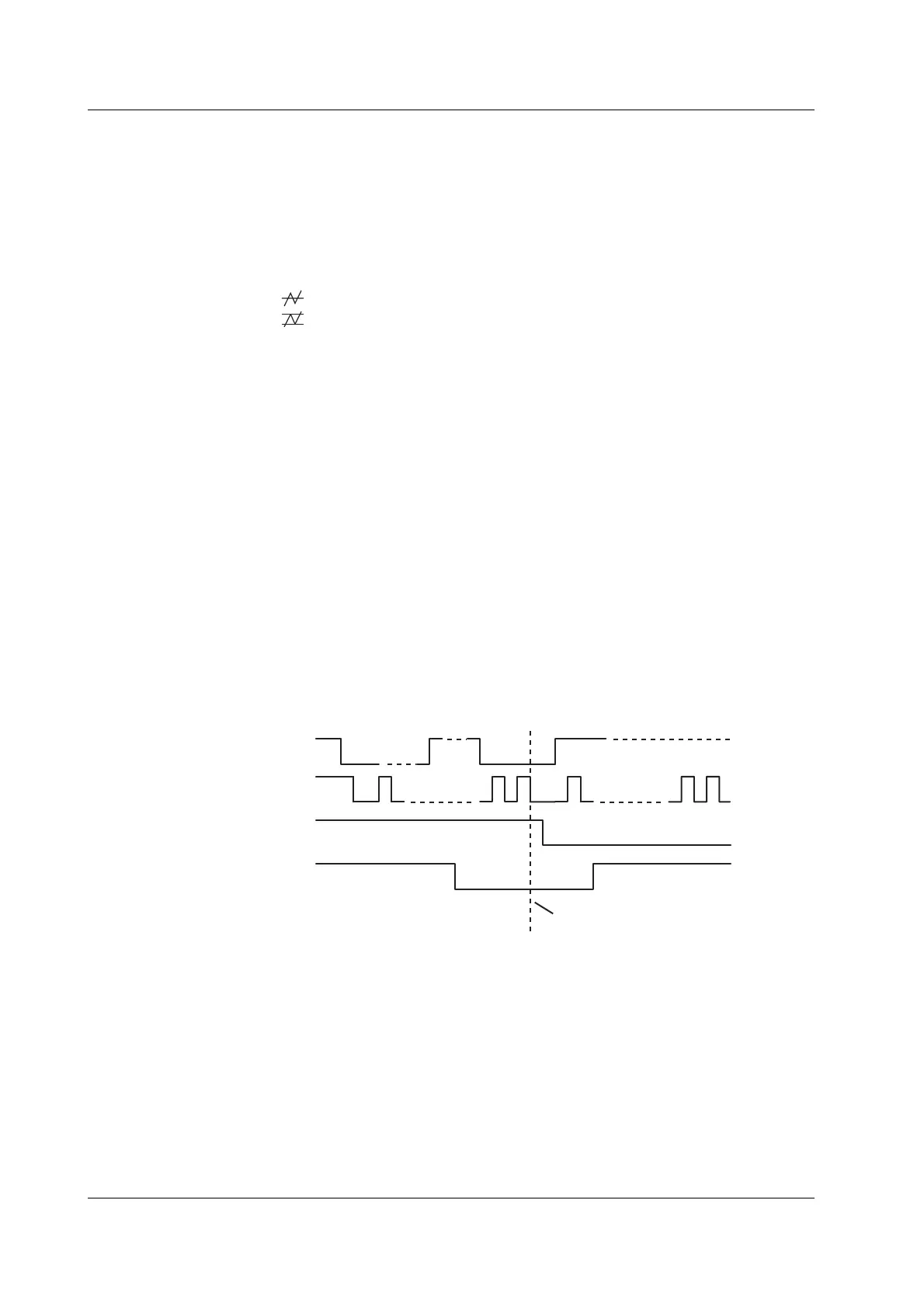
• I2C Only
This setting is used when activating the trigger based only on the SCL/SDA signal
(the I
2
C bus trigger condition).
891 189
I
2
C bus condition met
SDA
SCL
CH3
CH4
.....
..... .....
.....
.....
Condition met
Trigger activated here
CH3 and CH4 are irrelevant
1.3 Setting the Trigger Conditions

 Loading...


