<3. Installation>
32
IM01C25A01-01E
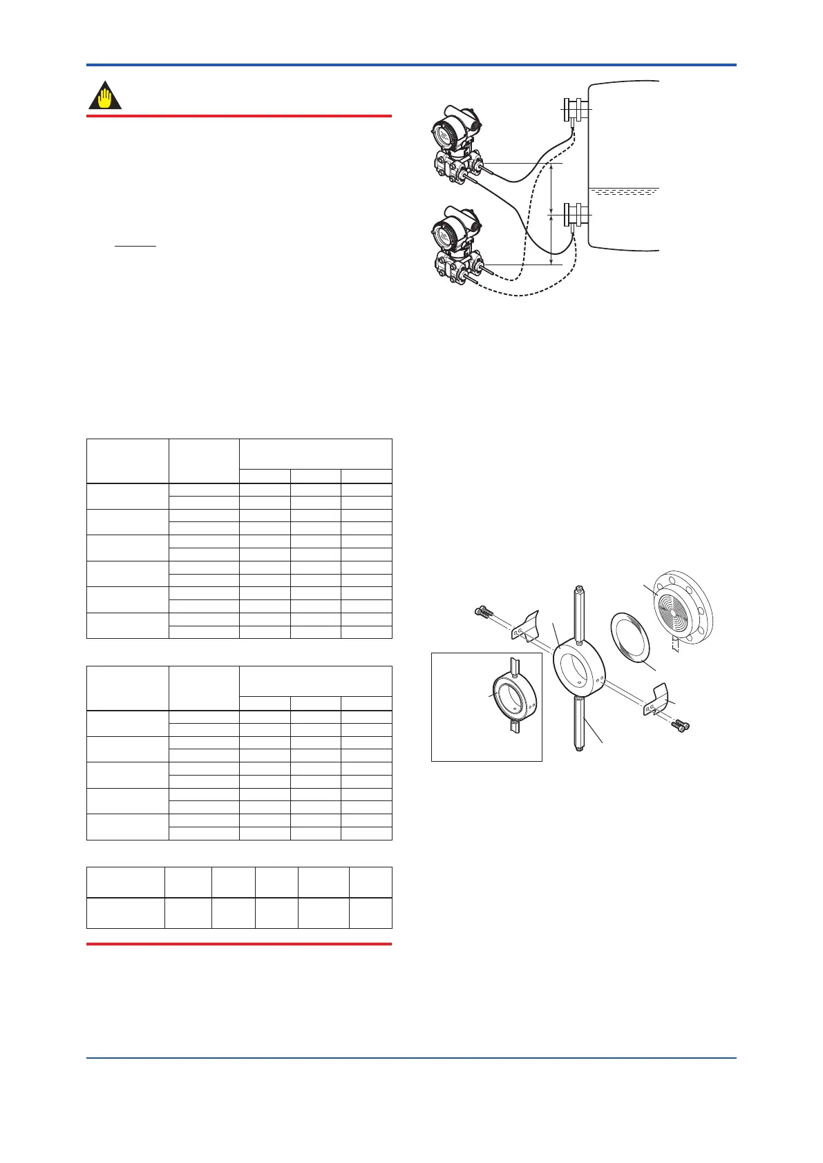
IMPORTANT
Thetransmittershouldbeinstalledatleast600mmbelow
thehighpressure(HP)processconnectiontoensurea
positiveheadpressureoflluid.Payspecialattentionto
vacuum applications.
Ifitcannotbeinstalledatleast600mmbelowtheHP
processconnection,pleaseusetheequationbelow:
h= × 0.102 [mm]
(P–P0)
ds
h: VerticalheightbetweentheHPprocessconnection
andthetransmitter(mm)
h≤0:Installthetransmitteratleasth(mm)belowthe
HP process connection
h>0:Installthetransmitteratmosth(mm)abovethe
HP process connection
P: Pressureinthetank(Paabs)
P0:Minimumworkingpressurelimitofthetransmitter(Pa
abs)Seebelowtable.
[ForlluidcodeA,B,C,D,E]
Wetted parts
material
code
Capillary
length
Process connection size
code
2, 8 3 4,W
SW
1 to 5m 6790 3190
6 to 10m 10030 3520
SE
1 to 5m 6790 3190
6 to 10m 10030 3520
SY
1 to 5m 3190
6 to 10m 3520
HW
1 to 5m 19150 6140
6 to 10m 8290
TW
1 to 5m 9620 3620
6 to 10m 4210
UW
1 to 5m 9540 4750
6 to 10m 6050
[Forlluidcode1,2,4]
Wetted parts
material
code
Capillary
length
Process connection size
code
2, 8 3 4,W
SW
1 to 5m 2570 320
6 to 10m 4680 530
SE
1 to 5m 2570 320
6 to 10m 4680 530
SY
1 to 5m 320
6 to 10m 530
HW
1 to 5m 10220 2050
6 to 10m 3450
TW
1 to 5m 4270 570
6 to 10m 960
ds:Specicgravityoflluid(at25°C).Seebelowtable.
Filluid
code
A, 1, 4 B C, 2 D E
ds:Specic
gravity
1.07 0.94 1.09
1.90 to
1.92
1.09
F0308.ai
P
Low pressure side
High
pressure
side
(+)
(–)
0
h
Figure 3.8 Example of Installation to Tank
(Caution on Installation)
3.4 Mounting the Flushing
Connection Ring
3.4.1 Mounting to Pressure Detector
Section
Theushingconnectionringismountedtothepressure
detectorsectionasshowninFigure3.9.
Atthefactoryshipment,theushingconnectionringis
alreadyassembledandattachedtoprocessdetector
section.
Ring holder
Spiral gasket
F0309.ai
View from pressure
detector section
Groove for
installing
spiral gasket
Pressure-detector section
Vent/Drain plug
Ring
Figure 3.9 Mounting to Pressure Detector Section
(1)Mounttheringholderontheringandlooselytighten
themountingscrews.
(2)Placethespiralgasketintheringgroove.Withthe
ringcorrectlyalignedandushwiththefaceofthe
pressuredetector,securelytighteneachringholder’s
mounting screws.
(3)Positiontheringsothatthevent/drainplugsare
alignedstraightupanddown.
 Loading...


