<6. Operation>
48
IM01C25A01-01E
6. Operation
NOTE
For FOUNDATIONFieldbus,PROFIBUSPAandModbus
communication types and forthetransmitteroperating
conrmationandzeroingbyanycommunication
method,refertoeachcommunicationmanual.
6.1 Preparation for Starting
Operation
ConrmingthatTransmitterisOperating
Properly
On the integral indicator
• Ifthewiringsystemisfaulty,thedisplaystaysblank.
• Ifthetransmitterisfaulty,anerrorcodeisdisplayed.
Self-diagnostic error
on the integral indicator
(Faulty transmitter)
F0601.ai
Verify and Change Transmitter
Parameter Setting and Values
Theparametersrelatedtothefollowingitemsaresetat
factoryasspeciedinorder.
• Calibrationrange
• Integralindicatordisplay
• Outputmode
• Softwaredamping(optional)
Otherparameterslikefollowingareshippedwiththe
default setting.
• Low-cut
• Processalarmsetting
• Staticpressurerange
• Signalcharacterizer
• Writeprotection
Toconrmorchangethevalues,pleaserefertoeach
communication manual.
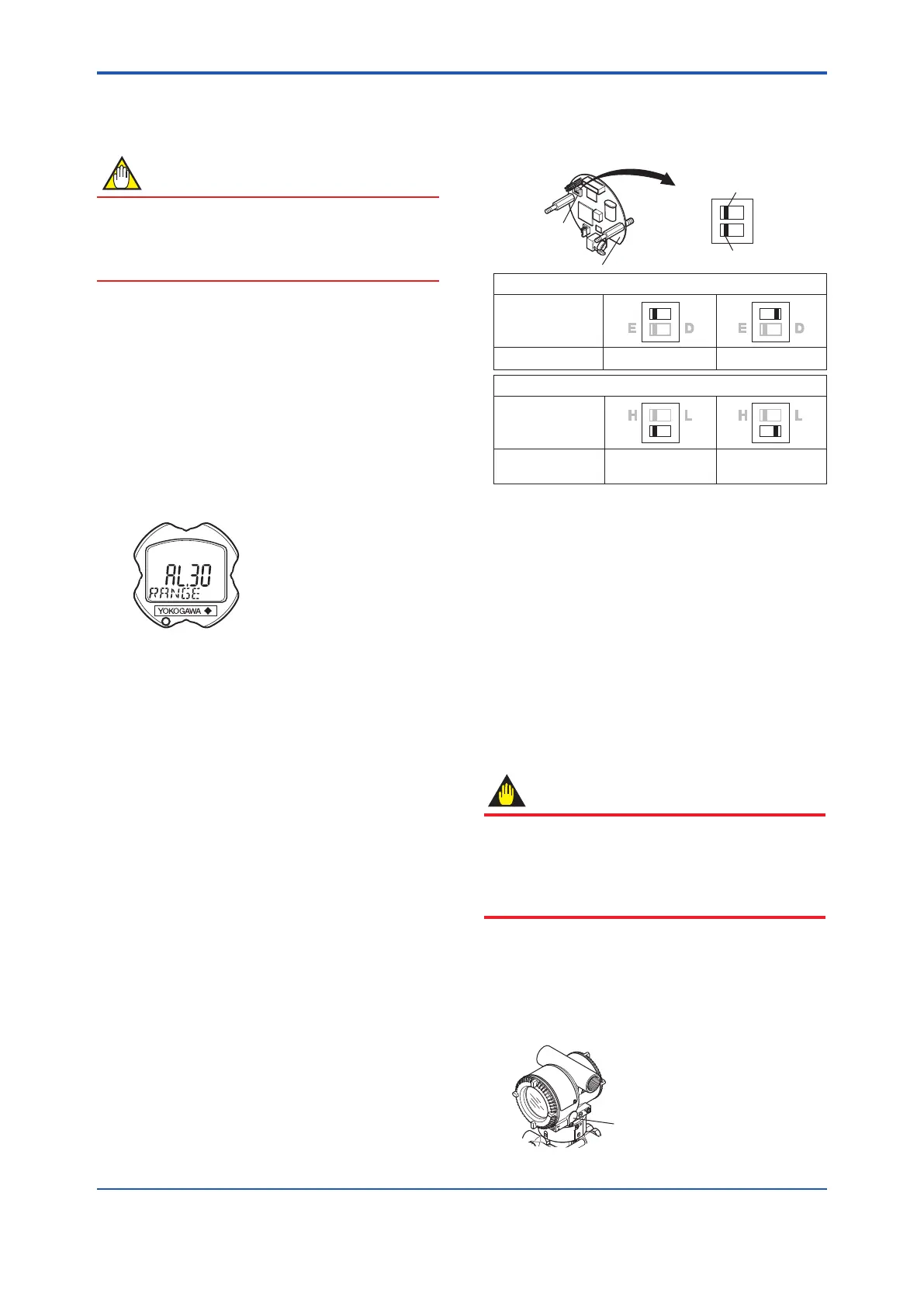
Output Status Setting at CPU Failure and
Hardware Write Protection
Settheswitchesasshowninthegurebelowtosetthe
burn-outdirectionandwriteprotection.TheBurnout
switchissettotheHsidefordelivery(unlessoptioncode
/C1or/C2isspeciedintheorder),andthehardware
writeprotectionswitchissettoEsideexceptEJX910A
andEJX930A.Thesettingoftheswitchescanbe
conrmedviacommunication.
F0602.ai
H L H L
Slide switch
CPU assembly
BO H L
WR E D
Burnout direction switch
Write protection switch
H L
H L
E D E D
Hardware write protection switch (WR)
Write Protection
Switch Position
HIGH LOW
Burnout direction switch (BO)
Burnout Direction
Burnout Direction
Switch Position
YES
(Write disabled)
NO
(Write enabled)
Write Protection
Figure 6.1 Burn-out Direction and Hardware Write
Protection Slide Switch
6.2 Zero Point Adjustment
Aftercompletingpreparationsforoperatingthe
transmitter,adjustthezeropoint.
Zeropointadjustmentcanbedonebyturningthe
transmitter’szero-adjustmentscreworbyusingthe
communicator.Thissectiondescribestheprocedure
forthezero-adjustmentscrew.Forthezero-adjustment
viacommunication,procedure,pleaserefertoeach
communication manual.
IMPORTANT
Donotturnoffthepowertothetransmitter
immediatelyafterperformingazeropointadjustment.
Poweringoffwithin30secondsofperformingthis
procedurewillreturnthezeropointtoitsprevious
setting.
6.2.1 Adjusting Zero Point for Differential
Pressure Transmitters
Beforeadjustingzeropoint,makesurethattheequalizing
valve is open.
Zero-adjustment screw cover
F0603.ai
Figure 6.2 External Zero Adjustment Screw
 Loading...


