<4. Installing Impulse Piping>
35
IM01C25A01-01E
4. Installing Impulse Piping
4.1 Impulse Piping Installation
Precautions
Theimpulsepipingthatconnectstheprocess
outputstothetransmittermustconveytheprocess
pressureaccurately.If,forexample,gascollectsin
aliquid-lledimpulseline,orthedrainofagas-lled
impulselinebecomesplugged,itwillnotconveythe
pressureaccurately.Sincethiswillcauseerrorsinthe
measurementoutput,selecttheproperpipingmethod
fortheprocessuid(gas,liquid,orsteam).Paycareful
attentiontothefollowingpointswhenroutingtheimpulse
pipingandconnectingtheimpulsepipingtoatransmitter.
4.1.1 Connecting Impulse Piping to the
Transmitter
(1) Check the High and Low Pressure
Connections on the Transmitter (Figure 4.1)
Symbols“H”and“L”havebeenplacedonthecapsule
assemblytoindicatehighandlowpressureside.With
differentialpressuretransmitters,connectthehigh
pressuresideimpulselinetothe“H”side,andthelow
pressuresideimpulselinetothe“L”side.
Withgauge/absolutepressuretransmitters,connectthe
impulselinetothe‘H’side.
F0401.ai
Process
connection
“H” and “L” are shown
Process connection
Process connector
Bolt
Differential Pressure Transmitter
Figure 4.1 “H” and “L” Symbols on a Capsule
Assembly
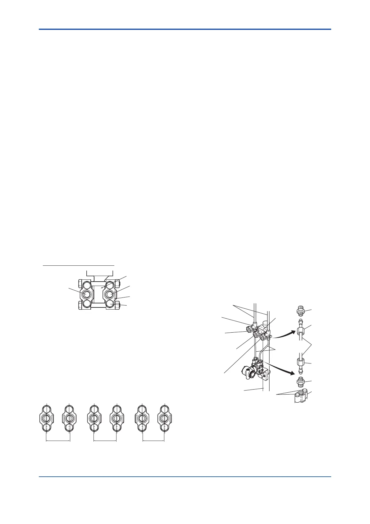
(2) Changing the Process Connector Piping
Connections (for differential pressure
transmitters)
Theimpulsepipingconnectiondistancescanbechanged
between51mm,54mmand57mmbychangingthe
orientationoftheprocessconnectors.
Thisisconvenientforaligningtheimpulselinewitha
process connectors.
57 mm 54 mm 51 mm
F0402.ai
Figure 4.2 Process Connector Impulse Piping
Connection Distances
(3) Tightening the Process Connector
Mounting Bolts
Afterconnectinganimpulseline,tightentheprocess
connectormountingboltsuniformly.
(4) Removing the Impulse Piping Connecting
Port Dustproof Cap
Theimpulsepipingconnectingportonthetransmitteris
coveredwithaplasticcaptokeepoutdust.Thiscapmust
beremovedbeforeconnectingtheline.(Becarefulnot
todamagethethreadswhenremovingthiscap.Never
insertascrewdriverorothertoolbetweenthecapand
portthreadstoremovethecap.)
(5) Connecting the Transmitter and 3-Valve
Manifold (for differential pressure
transmitters)
A3-valvemanifoldconsistsoftwostopvalvestoblock
processpressureandanequalizingvalvetoequalize
thepressuresonthehighandlowpressuresidesofthe
transmitter.Suchamanifoldmakesiteasiertodisconnect
thetransmitterfromtheimpulsepiping,andisconvenient
whenadjustingthetransmitterzeropoint.
Therearetwo3-valvemanifoldtyps:thepipe-mounting
typeandthedirect-mountingtype;careshouldbetaken
withrespecttothefollowingpointswhenconnectingthe
manifoldtothetransmitter.
Pipe-Mounting Type 3-Valve Manifold
F0403.ai
Nipple
Nipple
Process
connector
Ball head
lock nut
Pipe
Ball head
lock nut
Process
connector bolts
50 mm(2-inch) pipe
Pipes
3-valve
manifold
Impulse piping
Vent plug
(optional)
Stop valve
(low pressure side)
Equalizing valve
(balancing)
Stop valve
(high pressure side)
Figure 4.3 3-Valve Manifold (Pipe-Mounting Type)
 Loading...


