<4. Installing Impulse Piping>
38
IM01C25A01-01E
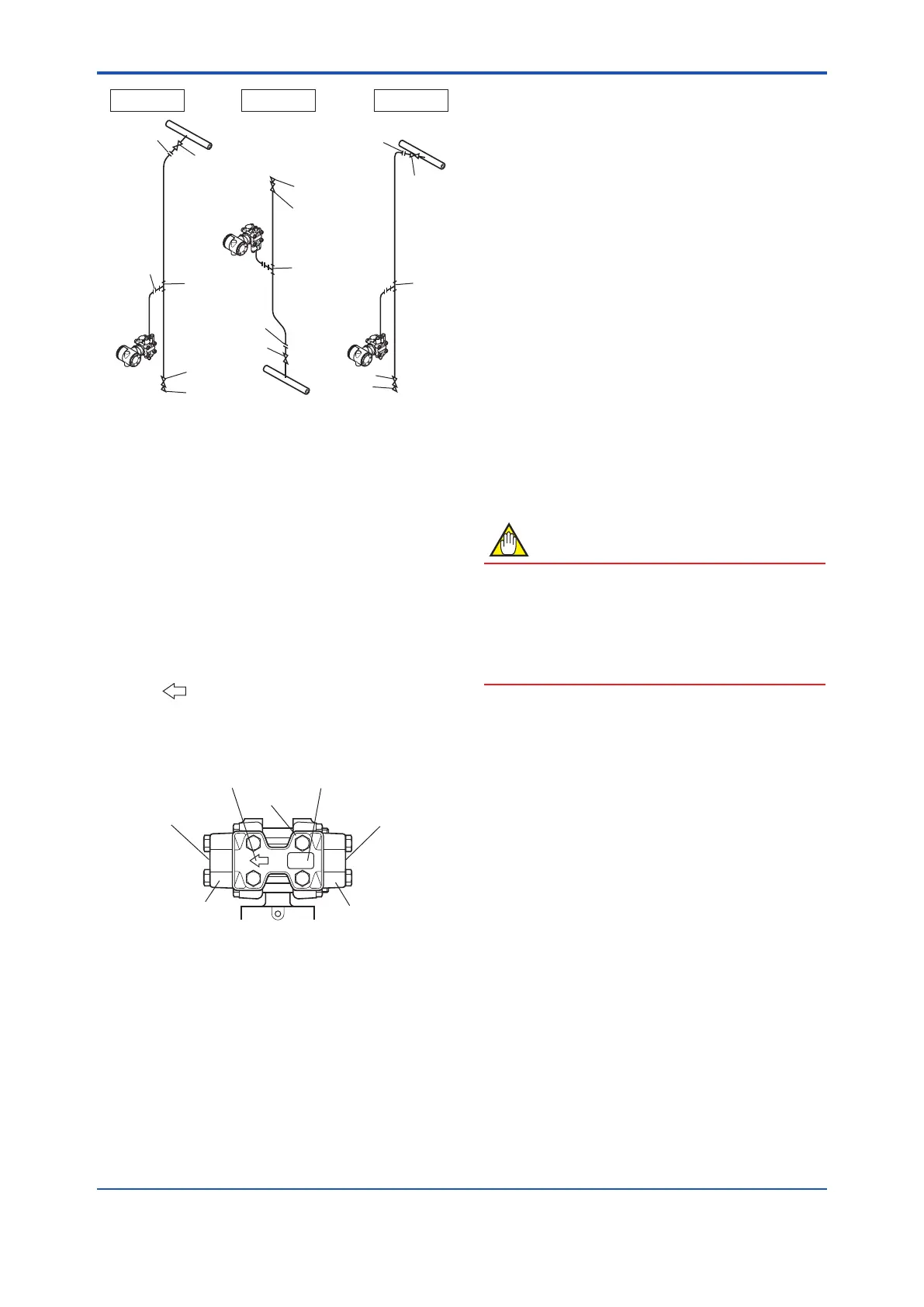
F0408.ai
Liquid
Gas Steam
Union or flange
Tee
Tee
Drain plug
Drain valve
Drain valve
Drain plug
Union or flange
Union or
flange
Union or flange
Tap valve
Tap valve
Tee
Drain valve
Drain plug
Tap valve
Figure 4.8 Impulse Piping Connection Examples
(for gauge/absolute pressure
transmitters)
4.3 Process Piping Installation
Precautions (EJ115)
4.3.1 Connecting Process Piping to the
Transmitter
(1) ConrmingtheProcessFluidFlow
Direction
Themark“ ”onthemanifoldindicatesthedirectionin
whichtheprocessuidisowed(fromrighttoleft).
Whenconnectingtheprocesspipingtotheprocess
connector,conrmtheprocessuidowdirection.
F0409.ai
Flow direction (from right to left)
Manifold
Orifice name plate
Process connector
(low pressure side)
Process connector
(high pressure side)
Process connection
(outflow side)
Process connection
(inflow side)
Figure 4.9 Manifold and Flow Direction Indication
(2) Tightening the Process Connector
Mounting Bolts
Thetransmitterisshippedwiththeprocessconnector
mountingboltsonlylooselytightened.Afterconnecting
theprocesspiping,tightentheseboltsuniformlyto
preventleakswithatorqueof39to49N·m{4to5kgf·m}.
(3) Removing the Process Connector Port
Dustproof Cap
Theprocessconnectorportthreadsarecoveredwitha
plasticcaptoexcludedust.Thiscapmustberemoved
beforeconnectingthepiping.(Becarefulnottodamage
thethreadswhenremovingthiscap.Neverinserta
screwdriverorothertoolbetweenthecapandport
threadstoremovethecap.)
4.3.2 Routing the Process Piping
(1) Relationship between Process Fluid
and Manifold Locations (For the vertical
impulse piping type)
Ifcondensate(orgas)generatedintheprocesspiping
wereallowedtoaccumulate,thenitwouldbenecessary
toremoveitperiodicallybyopeningthedrain(or
vent)plug.However,thiswouldgenerateatransient
disturbanceinthepressuremeasurement.Therefore,the
processpipingmustberoutedsothatanycondensate(or
gas)generatedintheprocesspipingwillnotaccumulate
inthepressure-sensingassemblyofthetransmitter.
NOTE
• Iftheprocessuidisagas,thenasarulethe
manifoldmustbelocatedatthedownsideofthe
pressure-sensingassembly.
• Iftheprocessuidisaliquid,thenasarulethe
manifoldmustbelocatedattheupsideofthe
pressure-sensingassembly.
(2) Pipe Size for Process Piping
Usea15mm(1/2-inch)pipeforprocesspiping
connectiontotheprocessconnector.
(3) Preventing Freezing
Ifthereisanyriskthattheprocessuidinthetransmitter
pressure-sensingassemblycouldfreezeorsolidify,use
asteamjacketorheatertomaintainthetemperatureof
theuid.
(4) Process Piping Connection Examples
Figure4.10showsexamplesoftypicalprocesspiping
connections.Beforeconnectingthetransmittertothe
process,studythetransmitterinstallationlocation,the
processpipinglayout,andthecharacteristicsofthe
processuid(corrosiveness,toxicity,ammability,etc.),in
ordertomakeappropriatechangesandadditionstothe
connectioncongurations.
Notethefollowingpointswhenreferringtothesepiping
examples.
• Theprocesspipingmaterialusedmustbecompatible
withtheprocesspressure,temperature,andother
conditions.
 Loading...


