<4. Installing Impulse Piping>
37
IM01C25A01-01E
(4) Temperature Difference Between Impulse
Piping (for differential pressure
transmitters)
Ifthereisatemperaturedifferencebetweenthehigh
andlowimpulselines,thedensitydifferenceoftheuids
inthetwolineswillcauseanerrorinthemeasurement
pressure.Whenmeasuringow,impulselinesmustbe
routedtogethersothatthereisnotemperaturedifference
betweenthem.
(5) Condensate Pots for Steam Flow
Measurement (for differential pressure
transmitters)
Iftheliquidintheimpulsepipingrepeatedlycondenses
orvaporizesasaresultofchangesintheambientor
processtemperature,thiswillcauseadifferenceinthe
uidheadbetweenthehighpressureandlowpressure
sides.Topreventmeasurementerrorsduetothesehead
differences,condensatepotsareusedwhenmeasuring
steamow.
(6) Preventing Wind Speed Effects in Very Low
Differential Pressure Measurement
(for differential pressure transmitters)
IMPORTANT
Whenusingadifferentialpressuretransmitterto
measureverylowpressures(draftpressure),thelow
pressureconnectionportisleftopentoatmospheric
pressure(thereferencepressure).
Anywindaroundthedifferentialpressuretransmitter
willthereforecauseerrorsinthemeasurement.To
preventthis,itwillbenecessaryeithertoenclosethe
transmitterinabox,ortoconnectaimpulselineto
thelowpressuresideandinsertitsendintoawind
excludingpot(cylindricalwithabaseplate).
(7) Preventing Freezing
Ifthereisanyriskthattheprocessuidintheimpulse
pipingortransmittercouldfreeze,useasteamjacketor
heatertomaintainthetemperatureoftheuid.
NOTE
Aftercompletingtheconnections,closethevalveson
theprocesspressuretaps(mainvalves),thevalvesat
thetransmitter(stopvalves),andtheimpulsepiping
drainvalves,sothatcondensate,sediment,dustand
otherextraneousmaterialcannotentertheimpulse
piping.
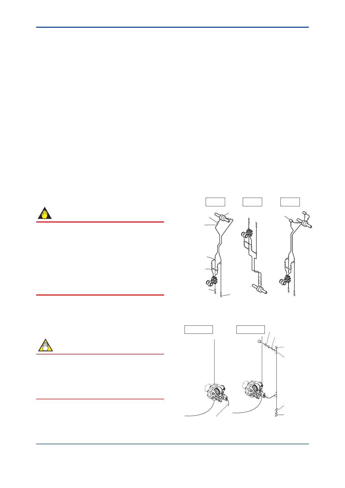
4.2 Impulse Piping Connection
Examples
Figure4.6,4.7,and4.8showsexamplesoftypical
impulsepipingconnections.Beforeconnectingthe
transmittertotheprocess,studythetransmitter
installationlocation,theprocesspipinglayout,and
thecharacteristicsoftheprocessuid(corrosiveness,
toxicity,ammability,etc.),inordertomakeappropriate
changesandadditionstotheconnectioncongurations.
Notethefollowingpointswhenreferringtothesepiping
examples.
• Iftheimpulselineislong,bracingorsupportsshould
beprovidedtopreventvibration.
• Theimpulsepipingmaterialusedmustbecompatible
withtheprocesspressure,temperature,andother
conditions.
• Avarietyofprocesspressuretapvalves(mainvalves)
areavailableaccordingtothetypeofconnection
(anged,screwed,welded),construction(globe,gate,
orballvalve),temperatureandpressure.Selectthe
typeofvalvemostappropriatefortheapplication.
Tee
3-valve
manifold
Drain valve
Orifice
Drain plug
Tap valve
Union
or flange
Liguid Gas
Condensate pot
Steam
F0406.ai
Figure 4.6 Impulse Piping Connection Examples
(for differential pressure transmitters)
F0407.ai
Pipe (opened to atmosphere
at low pressure side)
Open Tank
Closed Tank
Tap valve
Union or flange
Vent plug
Tee
Drain valve
Drain plug
Figure 4.7 Impulse Piping Connection Examples
(EJ210)
 Loading...


