<6. Operation>
49
IM01C25A01-01E
Thezero-adjustmentscrewislocatedinsidethecover.
Useaslottedscrewdrivertoturnthezero-adjustment
screw.Equalizethetransmitter,thenturnthescrew
clockwisetoincreasetheoutputorcounterclockwiseto
decreasetheoutput.Thezeropointadjustmentcanbe
madewitharesolutionof0.01%ofthesettingrange.The
degreeofzeroadjustmentsvarieswiththescrewturning
speed;turnthescrewslowlytomakeaneadjustment,
quicklytomakearoughadjustment.
Whenusingdifferentialpressuretransmittersforlevel
measurementandifyoucannotobtainthelowerrange
valuefromtheactualmeasurementvalueof0%,referto
subsection6.2.2(2).
6.2.2 Adjusting Zero Point for Gauge/
Absolute Pressure Transmitters
(1) When you can obtain the Low Range Value
from the actual measured value of 0%
(0 kPa, atmospheric pressure);
For pressure measurement using gauge pressure
transmitters,followthestepsbelowbeforeperforming
zeropointadjustment.
1) Closethetapvalve(mainvalve).
2) Loosenthellplugsothatthepressureappliedtothe
transmitterisonlytheheadofthesealliquid.
3) Adjustthezeropointatthisstatus.
4) Aftertheadjustment,closethellplugandthen
graduallyopenthetapvalve.
Useaslottedscrewdrivertoturnthezero-adjustment
screw.Turnthescrewclockwisetoincreasetheoutputor
counterclockwisetodecreasetheoutput.Thezeropoint
adjustmentcanbemadewitharesolutionof0.01%ofthe
settingrange.Sincethedegreeofthezeroadjustment
varieswiththescrewturningspeed,turnthescrewslowly
tomakeaneadjustmentandquicklytomakearough
adjustment.
(2) When you cannot obtain the Low Range
Value from the actual measured value of
0%;
Adjustthetransmitteroutputtotheactualmeasured
valueobtainedbyadigitalmanometeroraglassgauge.
[Example]
Themeasuringrangeof50to250kPa;theactual
measuredvalueof130kPa.
130–50
250–50
Actual measured value=
x100=40.0%
(=10.4mA)
Turnthescrewtomatchtheoutputsignaltotheactual
measured value.
6.3 Local Parameter Setting
WARNING
Thelocalpushbuttonontheintegralindicatormust
notbeusedinahazardousarea.Whenitisnecessary
tousethepushbutton,operateitinanon-hazardous
location.
IMPORTANT
• Donotturnoffthepowertothetransmitter
immediately after performing parameter setting.
Poweringoffwithin30secondsofperformingthis
procedurewillreturntheparametertoitsprevious
setting.
• TheparameterofExtSWmustbe“Enabled”
toperformthisconguration.Seetheuser’s
manualIM01C25T(HART/BRAIN)forthesetting
procedure.
• TheLocalParameterSettingfunctionisavailable
withHARTorBRAINcommunicationtype.
6.3.1 Local Parameter Setting (LPS)
Overview
Parametercongurationbytheexternaladjustment
screwandpushbutton(integralindicatorcodeE)offers
easyandquicksetupforparametersofTagnumber,Unit,
LRV,URV,Damping,Outputmode(linear/squareroot),
Displayout1,andRe-rangebyapplyingactualpressure
(LRV/URV).Thereisnoeffectonmeasurementsignal
(analogoutputorcommunicationsignal)whenLocal
Parameter Setting is carried out.
External adjustment screw cover
F0604.ai
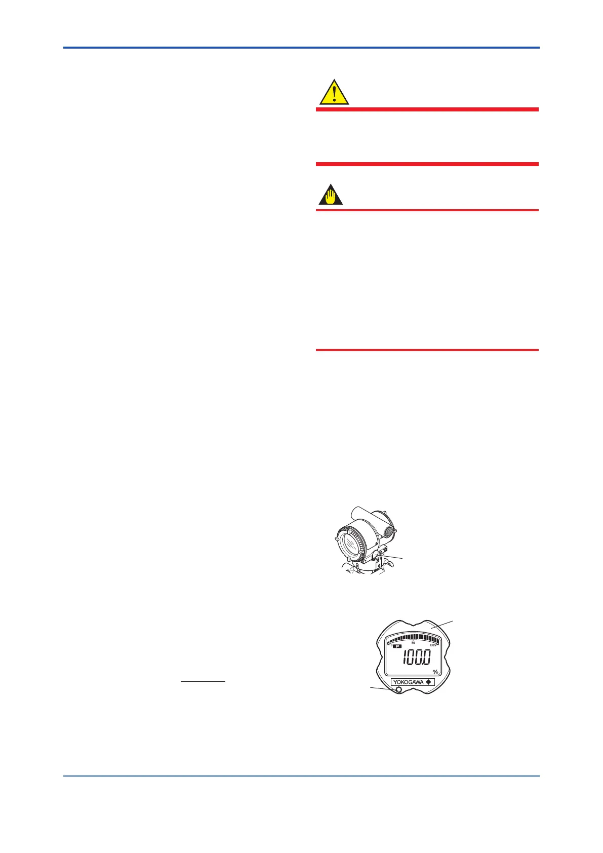
Figure 6.3 External Adjustment Screw
Integral indicator
Push-button
F0605.ai
Figure 6.4 Range –Setting Switch (push button)
 Loading...


