<5. Wiring>
44
IM01C25A01-01E
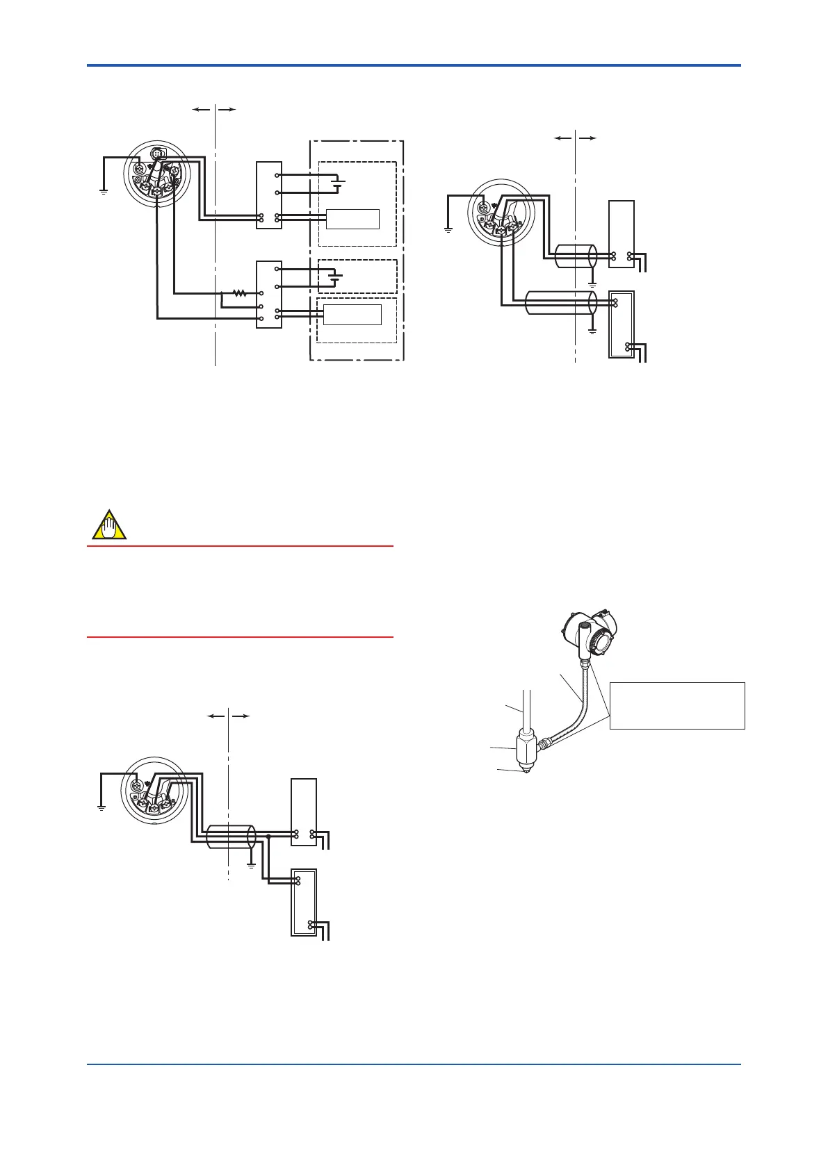
• SimultaneousAnalog-PulseOutput
Hazardous Location Nonhazardous Location
Transmitter terminal box
Safety barrier
(Isolated type)
I/O module
F0510.ai
Safety barrier
(Isolated type)
Power
supply
Power
supply
Analog input
Pulse input
Figure 5.12 Connection between Transmitter,
barrier and receiver
(4) 1 to 5 V output
Eitherthreeorfourwiresystemcanbeused.
Power supply line and 1 to 5 V signal line commonly use
theSUPPLY-terminal.
NOTE
Withthreewireconnection,thecablelengthmay
affectthemeasurementaccuracyoftheoutputsignal.
Ineitherthree-wireorfour-wireconnection,
recommendedwiringdistanceis200morless,and
theuseofshieldedcableisrecommended.
• Threewireconnection
Anegativewiringshallbecommonlyusedforpower
supply and signal line.
F0529.ai
Hazardous Location Nonhazardous Location
Transmitter terminal box
Distributor
(Power supply unit)
Receiver
instrument
Figure 5.13 Connection between Transmitter,
Distributor and Receiver
• Fourwireconnection
Fastenthenegativesidewiringofbothpowersupply
andsignallinetotheSUPPLY-terminal.
Hazardous Location Nonhazardous Location
Transmitter terminal box
Distributor
(Power supply unit)
Receiver
instrument
F0530.ai
Figure 5.14 Connection between Transmitter,
Distributor and Receiver
5.3.2 Wiring Installation
(1) General-use Type and Intrinsically Safe
Type
Withthecablewiring,useametallicconduitorwaterproof
glands.
• Applyanon-hardeningsealanttotheterminalbox
connectionportandtothethreadsontheexible
metalconduitforwaterproong.
F0511.ai
Flexible metal conduit
Wiring metal
conduit
Tee
Drain plug
Apply a non-hardening
sealant to the threads for
waterproofing.
Figure 5.15 Typical Wiring Using Flexible Metal
Conduit
 Loading...


