<Appendix2.ThermalElements>
A2-5
IM 02M04B01-01EN
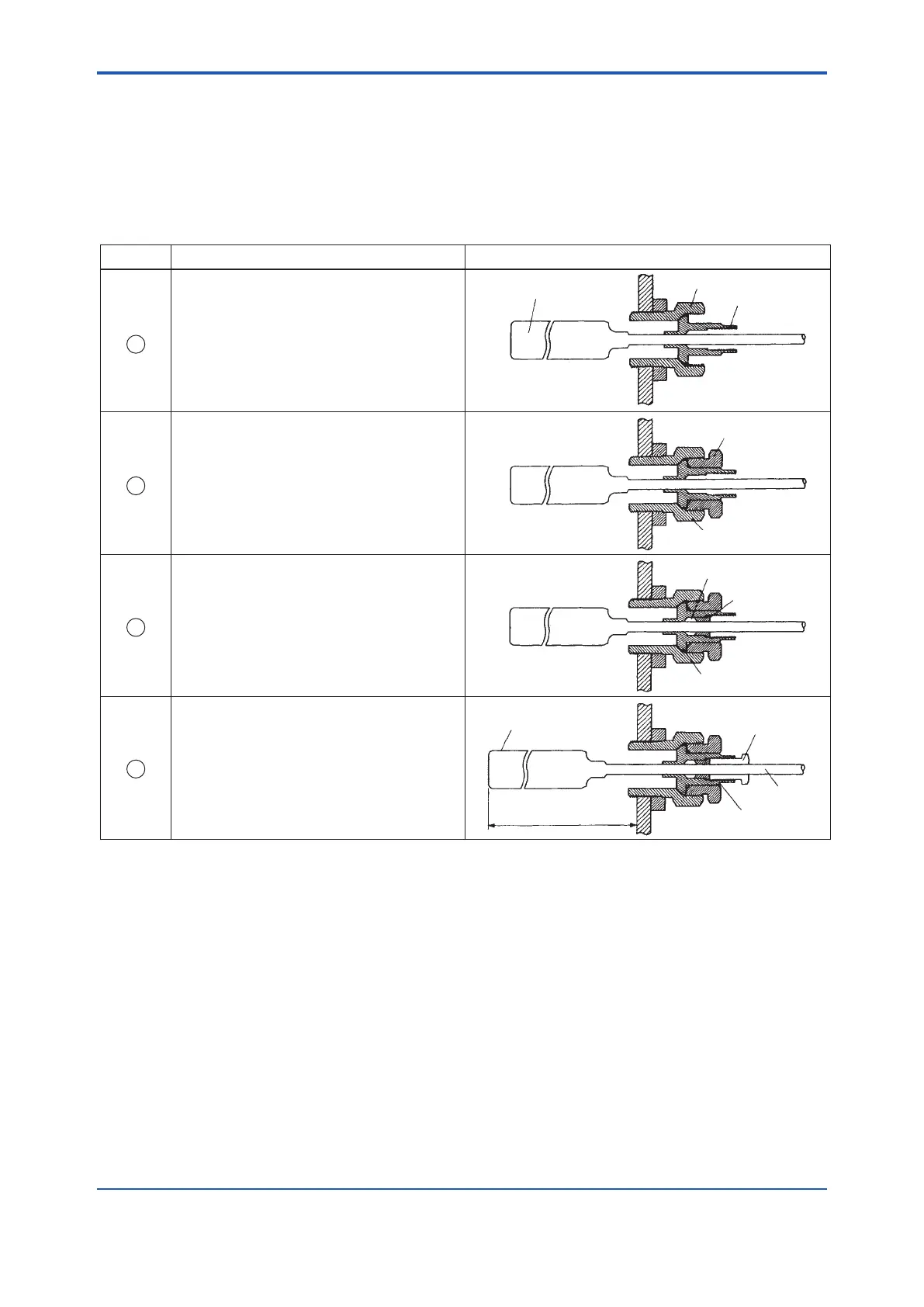
(5) Assembly/DisassemblyoftheAdjustableUnion
The adjustable union consists of a bushing, jam nut, spindle, gland nut, gland and packing.
With air set, packing is attached to it.
Without air set, packing is attached to bracket.
• AssemblingtheAdjustableUnion
Follow the steps summarized in the table below to assemble the union.
FA0218.ai
Thermo-sensitive bulb
Bushing
Spindle
Jam nut
Packing
Gland
Spindle
Bushing
Thermo-sensitive bulb
Insertion length
Gland nut
Capillary
Spindle
Step. No. Instruction Sectional View of Adjustable Union
4
3
2
1
Screw the bushing into the mounting hole of
a pipe or tank wall. Next, insert the spindle
into the bushing.
Screw the jam nut into the bushing to fix the
spindle.
Note: When handling the spindle, see the
cautionary note, “Handling the Flattened
Sides of the Spindle,” that follows this
table.
Check the insertion length of the
thermosensitive bulb. Screw the gland nut
into the spindle to fix the capillary.
Force the packing and gland into the
spindle.
Refer to below figure for the installation of
packing.
 Loading...


