<Appendix2.ThermalElements>
A2-6
IM 02M04B01-01EN
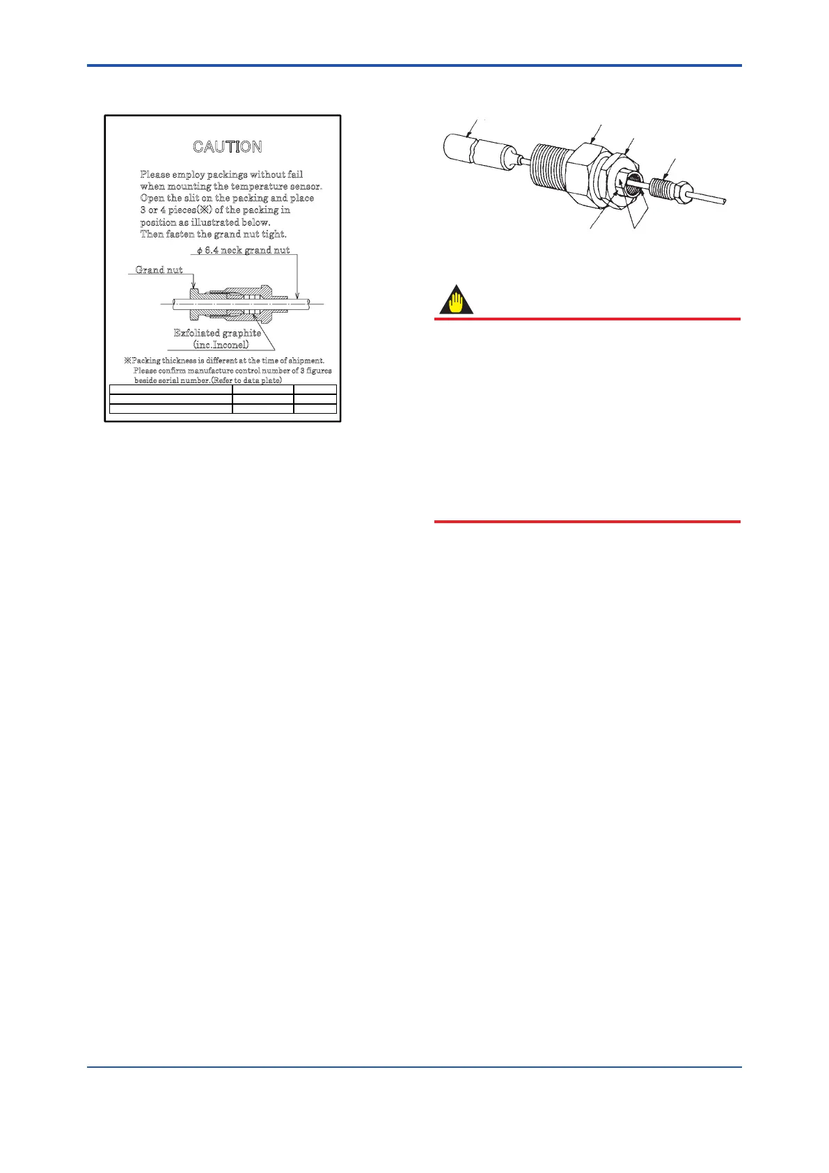
• InstallationofthePacking
CAUTION
Please employ packings without fail
when mounting the temperature sensor.
Open the slit on the packing and place
3
or 4 pieces(※) of the packing in
p
osition as illustrated below.
T
hen fasten the grand nut tight.
※Packing thickness is different at the time of shipment.
Please confirm manufacture control number of 3 figures
b
eside serial number.(Refer to data plate)
φ6.4 neck grand nut
Exfoliated graphite
(inc.Inconel)
Grand nut
Manufacture control number
thickness(mm)
Qty
Until 405 (year 2014) 4.5 2 or 3
On and after 406 (year 2014) 3.0 3 or 4
FB0120.
df
• DisassemblingtheAdjustableUnion
To disassemble the union, follow the steps in
the table above exactly in their reverse order.
• HandlingtheFlattenedSidesoftheSpindle
FA0219.ai
Thermo-sensitive bulb
Bushing
Jam nut
Gland nut
Flattened sides of spindle
Spindle
Adjustable Union
IMPORTANT
The spindle has two attened sides, as shown in
the gure on the left. These sides are provided
to enable you to properly lock the spindle (with
a wrench, etc.) when fastening or loosening the
gland nut. Do not apply force upon them for any
other purposes. Any excess force can deform
the sides because their walls are thin. Do NOT
apply such force especially when the gland nut
has been removed. When removing the spindle,
ALWAYS remove the jam nut rst and then pull
the spindle out by hand.

 Loading...


