IM 12D08B02-01E
Specifications 2-1
2-1. Specifications
A. Input specifications
: Two or four electrodes measurement with
square wave excitation. Cell constants from
0.008 to 50 cm
-
1
.
B. Detection method
: Frequency, read-pulse position and reference
voltage are dynamically optimized.
C. Input ranges
- Conductivity :
Minimum : 0 S/cm
Maximum : 200 mS x (Cell constant)
(overrange 1999 mS / cm).
- Resistivity :
Minimum : 0.005 k/ (Cell constant)
Maximum : 999 M x cm
- Temperature
Pt1000 : -20 to +250 °C (0 to 500 °F)
Pt100 and Ni100 : -20 to +200 °C (0 to 400 °F)
8K55 NTC : -10 to +120 °C (10 to 250 °F)
PB36 NTC : -20 to +120 °C (0 to 250 °F)
D. Output Span
- Conductivity : - min 0.01S/cm
: - max. 1999 mS/cm. (max 90%
zero suppression)
- Resistivity : - min 0.001kxcm
: - max. 999 M x cm. (max 90%
zero suppression)
E. Transmission Signal
: Isolated output of 4-20 mA DC
Burn up (21 mA) or Burn down
(3.6 mA when HART® or distributor comm. is
non-used, 3.9 mA when HART® or distributor
comm. is used) or pulse of 21 mA to signal
failure.
F. Temperature compensation
: Automatic, for temperature ranges mentioned
under C (inputs).
- Reference temp.
:
programmable from 0 to 100 °C or 30 to 210 °F
(default 25 °C).
G. Compensation algorithm
-NaCl :
According IEC 60746-3 NaCl tables
(default).
-T.C. : Two independent user program-
mable temperature coefficients,
from -0.0% to 3.5% per °C (°F)
by adjustment or calibration.
- Matrix :
Conductivity function of concentra-
tion and temperature. Choice out of
mAmA
mAmA
5 preprogrammed matrixes and a 25-
point user-programmable matrix.
H. Logbook
: Software record of important events and diag-
nostic data. Available through HART® link,
with diagnostic information available in the
display.
I. Display
: Custom liquid crystal display, with a main dis-
play of 31/2 digits 12.5 mm high. Message dis-
play of 6 alpha numeric characters, 7 mm high.
Warning flags and units (mS/cm, k·cm, S/
cm and M·cm) as appropriate.
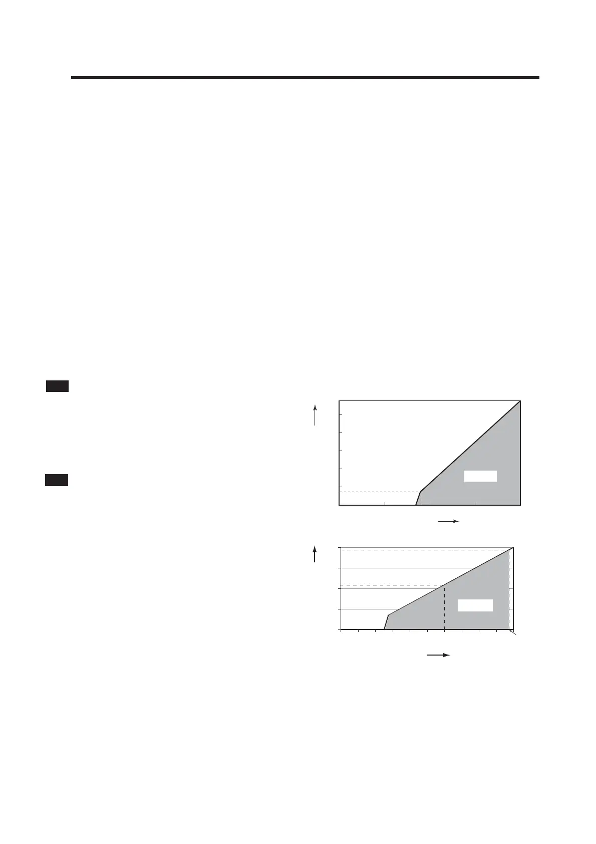
J. Power supply
: Nominal 24 volt DC loop powered system.
SC202G ; 17 to 40 volts, see Fig.2-1
SC202S : 17 to 31.5 volts, see Fig.2-2
Maximum load resistance
For the SC202G, see Fig. 1
200 or less with the PH201G
50 or less with the SDBT
For the SC202S, see Fig. 2-2
1000
1150
800
600
400
200
150
0
10 201817 30 400
Voltage (V)
Load Resistance ()
Possible
F06.EPS
Fig.2-1 Supply voltage/ load diagram for the SC202G
0
200
400
600
800
12 16
17
20 24 28 32
425
775
Voltage (V)
Load Resistance ()
31.5 V
Possible
Fig.2-2 Supply voltage/ load diagram for the SC202S
K. Input isolation
: 1000 VDC
L. Weight
Body weight : approx. 1.6 kg
Mounting brackets weight: approx. 0.7 kg.
2. GENERAL SPECIFICATIONS

 Loading...


