IM 12D08B02-01E
Installation and wiring 3-7
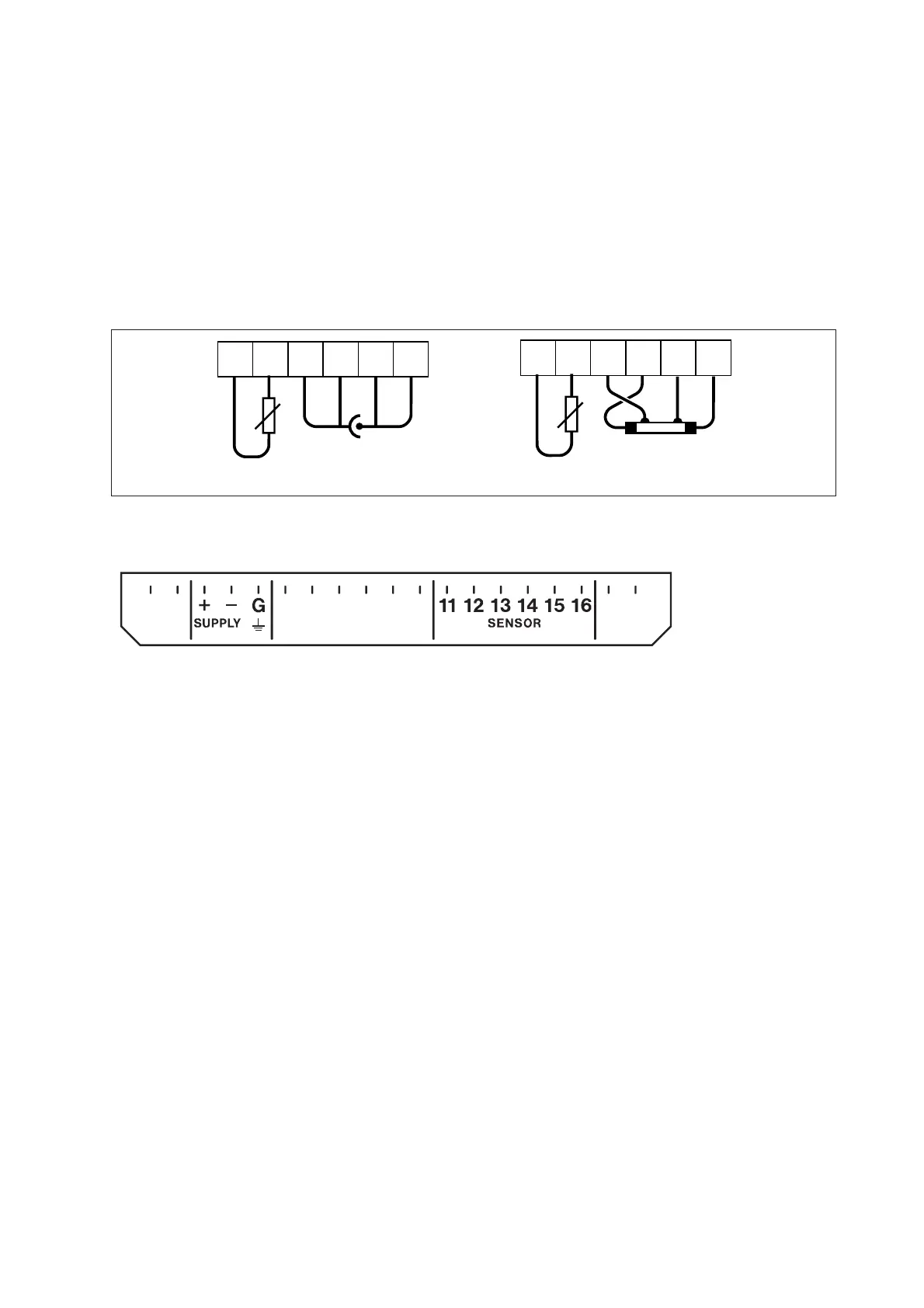
3-6. Other sensor systems
To connect other sensor systems, follow the general pattern of the terminal connections as listed below:
11 and 12 : Always used for temperature compensation resistor input.
13 and 14 : Normally used for the outer electrode
15 and 16 : Used for inner electrode
In case a 4-electrode measuring system will be used, 14 and 16 should be used for the current elec-
trodes.
Please ensure that shielded cabling will be used.
In figure 3-10 this is shown in a schematic way.
Figure 3-10. Connection diagram for other sensors
Figure 3-11. Terminal identification label
3-6-1. Sensor cable connections using junction box (BA10) and extension cable (WF10)
Where a convenient installation is not possible using the standard cables between sensors and transmit-
ter, a junction box and extension cable may be used. The Yokogawa BA10 junction box and the WF10
extension cable should be used. These items are manufactured to a very high standard and are neces-
sary to ensure that the specifications of the system are not compromised. The total cable length should
not exceed 60 metres (e.g. 5 m fixed cable and 55 m extension cable).
Note: 17 of both WF10 and BA10 do not need to be used.
11 12
13
14 15 16
t
11 12
13
14 15 16
t
2-electrode configuration
4-electrode configuration

 Loading...


