IM 12D08B02-01E
2-2 Appendix
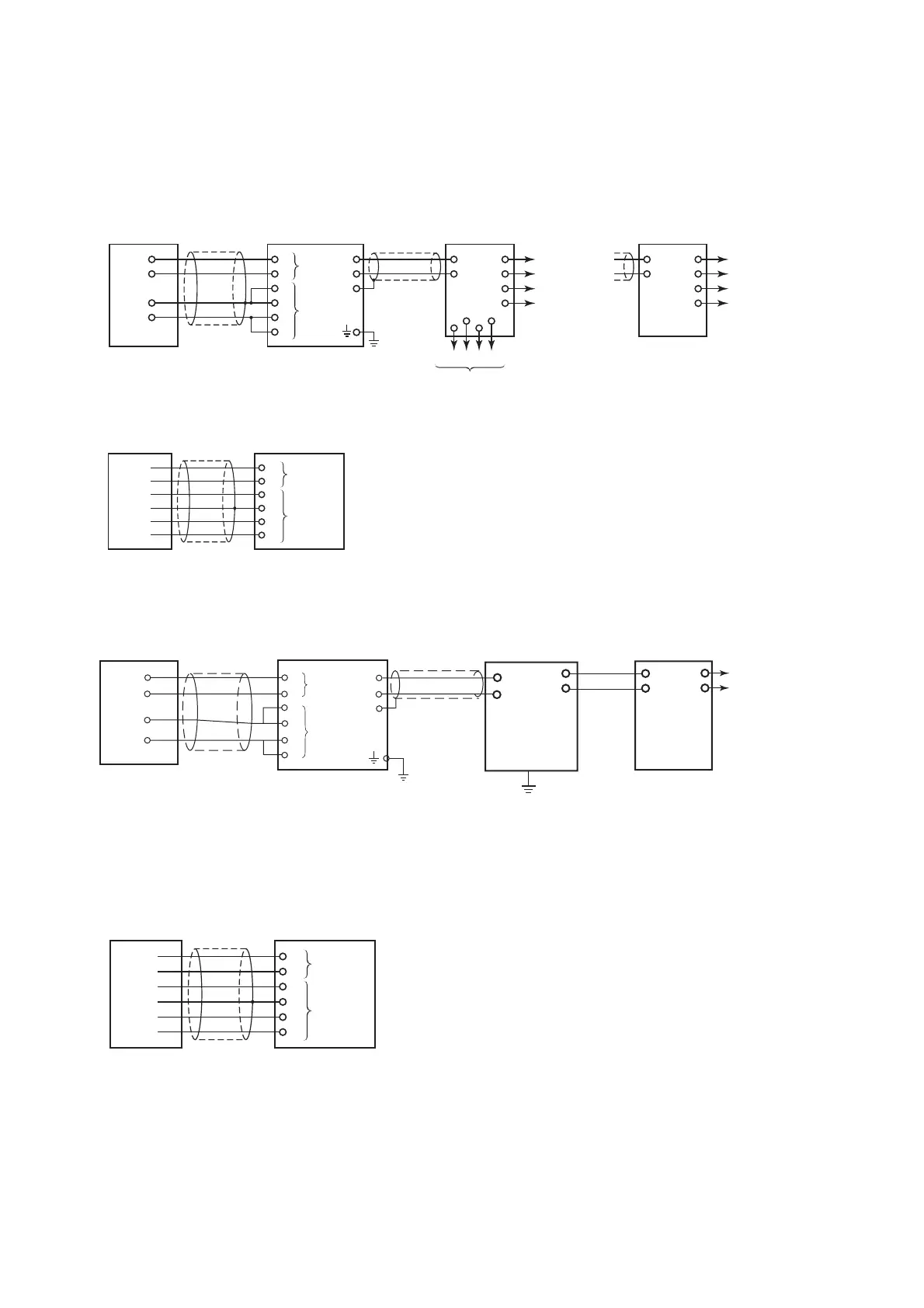
12-2. Wiring diagrams
1. Example of Non-Explosionproof System
(a) SC210G-A or SC210G-B
SC210G–A, SC210G–B
Conductivity sensor
SC202G
Conductivity transmitter
PH201G (Style B)
Dedicated distributor for EXA202
*1
*2
SDBT distributor
*2
11
Temper-
ature
sensor
Electrode
T1 11
T1
12
T2 12
T2
13
13
14
C1 14
C1
15
+
–
Output
(1 to 5V DC)
A(+)
B(
–)
+
–
Output
(1 to 5V DC)
C
D
F
H
HOLD FAIL
Relay contacts
b
a
d
c
+
–
G
C2 15
C2
16
Ground
16
Output
(1 to 5V DC)
+
–
Output
(1 to 5V DC)
+
–
1(+)
2(
–)
A
B
F
H
F08.EPS
*3 (100 or less)
(b) SC4AJ, SC8SG
SC4AJ, SC8SG
Conductivity sensor
*1
11
11
12
12
13
13
14
14
15
15
16
16
F09.EPS
Temperature
sensor
Conductivity
sensor
*1 : This cable is specified by the additional code of an conductivity sensor.
*2 : Use a two-conductor shielded cable of OD 6 to 12mm.
The cable length is : Max. 2000m (also the minimum operating voltage of conductivity
transmitter must be obtained)
*3 : Conduct grounding without fail on the conductivity transmitter
(Grounding reistance : 100 ½ or less)
SC202G
Conductivity transmitter
2. Example of Intrinsically Safe Explosionproof System
(a) SC210G-A or SC210G-B
SC210G-A,SC210G-B
Conductivity sensor
T1
T2
C1
C2
T1
T2
C1
C2
*1
11
12
13
14
15
16
11
12
13
14
15
16
SC202S
Conductivity transmitter
Temper-
ature
sensor
Electrode
*2
Ground
to earth
+
-
G
Distributor
Safety Barrier
*1: This cable is specified by the additional code of an conductivity sensor.
*2: Use two-wire cable with OD (Outside Diameter) of 6 to 12 mm.
F007-1.eps
Output
(b) SC4AJ, SC8SG
SC4AJ, SC8SG
Conductivity sensor
*1
11
11
12
12
13
13
14
14
15
15
16
16
F09.EPS
Temperature
sensor
Conductivity
sensor
*1 : This cable is specified by the additional code of an conductivity sensor.
SC202S
Conductivity transmitter

 Loading...


