IM 12D08B02-01E
Specifications 2-9
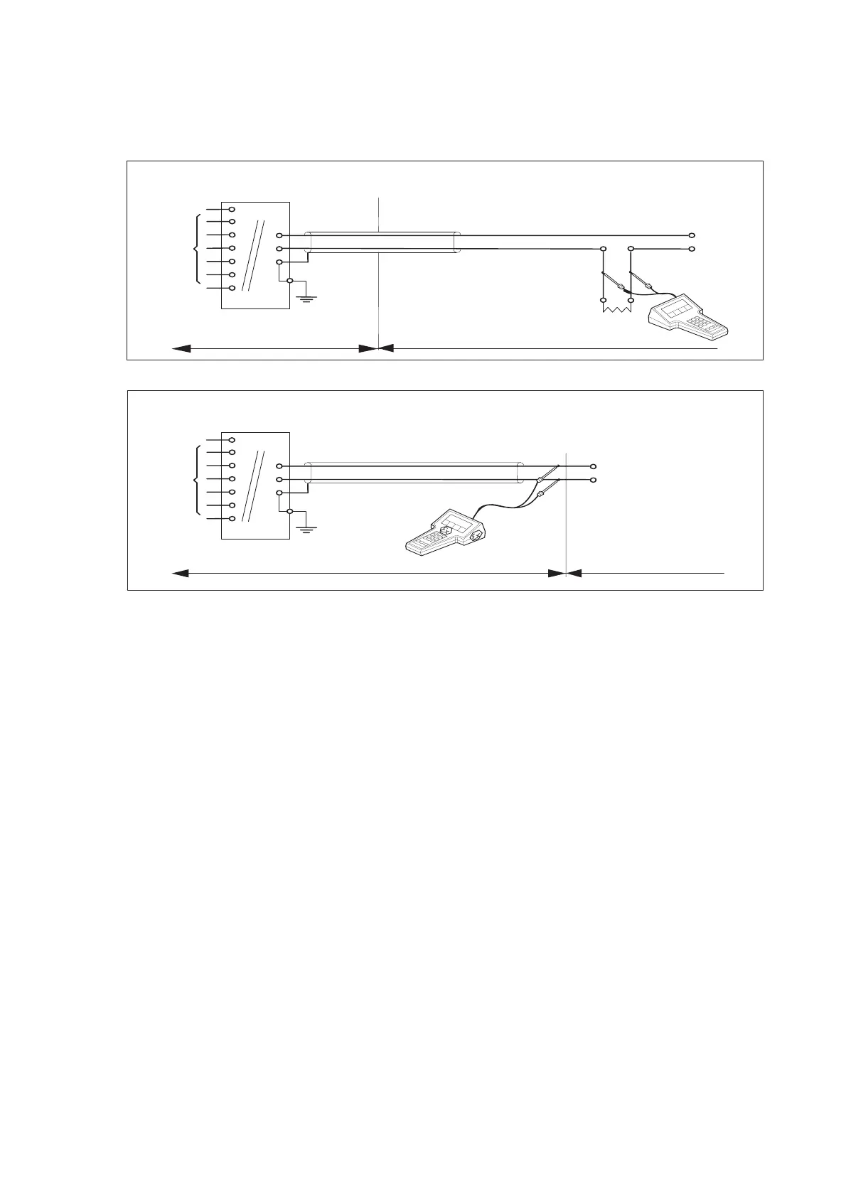
Sensor
terminals 11-16
Max. cablelength: 60 mtr.
Cable dia. : 3…12 mm.
Sensor
terminals 11-16
Max. cablelength: 60 mtr.
Cable dia.: 3…12 mm
Ùnclassified Location
+
G
Classified Location Unclassified Location
+
G
earth
onincendive design
FM Class I, Div.2, Group ABC D, T4 for ambient temp. < 55°C
T6 for ambient temp. < 40°C
SC202S transmitter
+
-
Load
Resistance
Classified Location
earth
FM Approved
power supply
Voc ≦ 31.5 V DC
For electrical data:
see text below.
For electrical data:
see text below.
onincendive design
FM Class I, Div.2, Group ABCD, T4 for ambient temp. < 55°C
T6 for ambient temp. < 40°C
SC202S transmitter
+
-
FM Approved
power supply
Voc ≦ 31.5 VDC
Functional
Functional
・ Electrical data of the SC202S.
- Supply circuit (terminals + and -):
Maximum input voltage Vmax = 31.5 V. Maximum input power P
max = 1.2 W
Effective internal capacitance Ci = 22 nF Effective internal inductance Li = 35 μH
- Sensor input circuit (terminals 11 through 16):
Maximum output voltage Vt = 14.4 V. Maximum output current It = 10 mA.
Maximum allowed external capacitance Ca = 1.71 μF.
Maximum allowed external inductance La = 600 mH.
・ The Hand Held Terminal must be FM Approved in case it is used in the classified location.
When installing this equipment, follow the manufacturers installation drawing.
Installation shall be in accordance with Article 501.4(B) of the National Electrical Code.
Non-incendive field wiring may be installed in accordance with Article 501 of the National
Electrical Code.
・ Grounding shall be in accordance with Article 250 of the National Electrical code
・ In case of using cable glands in Outdoor location, they shall be UV rated or made of metal.
WARNING
- Substitution of components may impair suitability for Division 2
- Do not remove or replace while circuit is live unless area is know to be non-hazardous
- Explosion Hazard – Do not disconnect equipment unless area is know to be
non-hazardous
- Do not reset circuit breaker unless power has been removed from the equipment or the
area is know to be non-hazardous
2-7. Control Drawing SC202S mA HART
®
Specifi cation (FM Non-incendive design)
Application Doc. No.: IKE026-A10 P.7 to P.8

 Loading...


