IM 12D08B02-01E
3-10 Appendix
2/3
QIS 12D08B02-61E
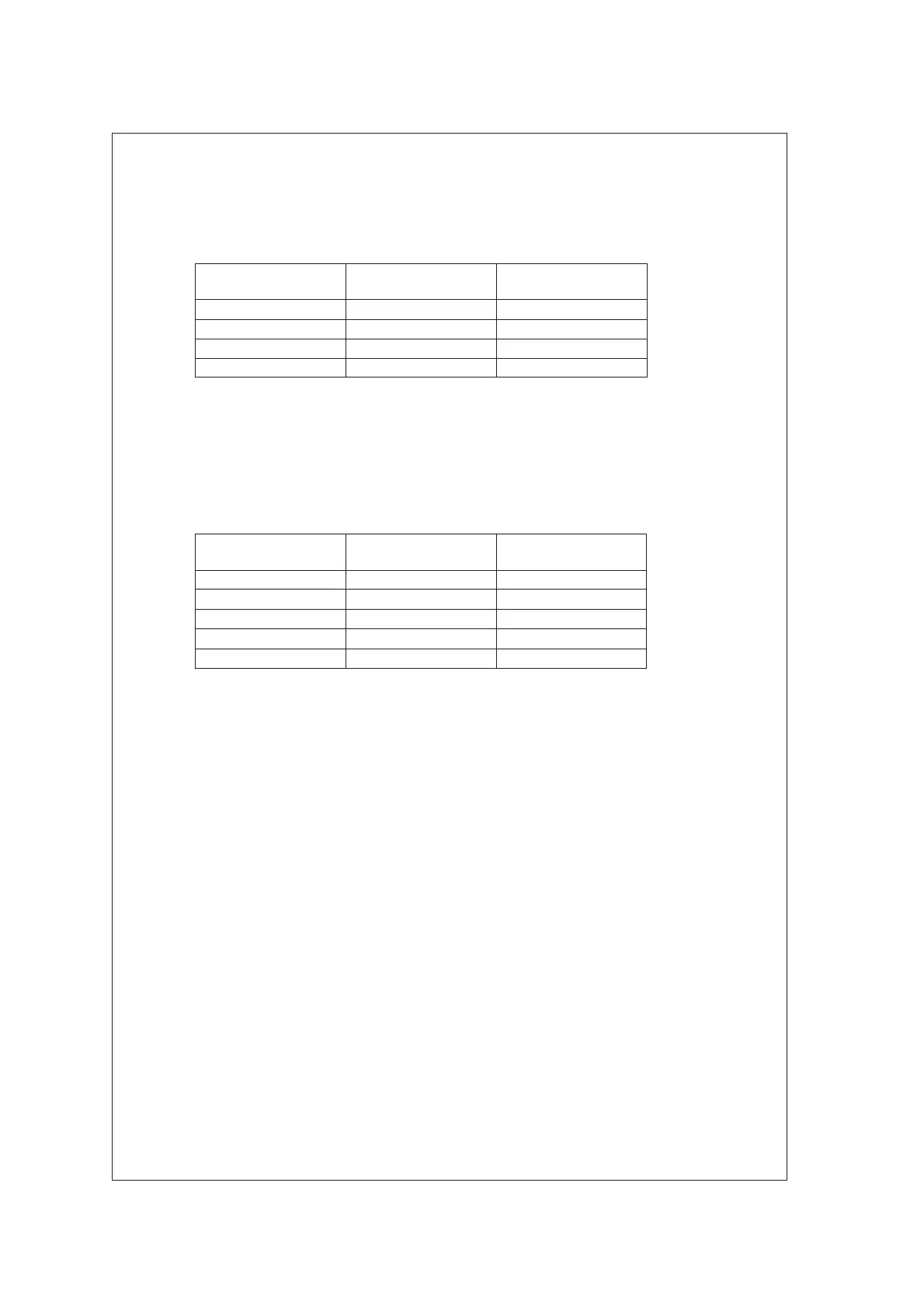
In this state, change the resistance value of the decade resistance box 1 as shown in Table 1.
The corresponding temperature indication must be within the range.
Table 1 Temperature Indication Check
Reference
Temperature
Resistance of
Resistance Box 1
Indication Range
–10 °C
960.9 :
–10 ±0.3 °C
75 °C
1289.8 :
75 ±0.3 °C
190 °C 1721.6 190 ±0.3 °C
240 °C 1904.6 240 ±0.3 °C
3.4 Conductivity Indication Check
Connect the instruments as shown in Figure 1, and set them as follows.
Decade resistance box 1: 100
Decade resistance box 2: 10
In this state, change the resistance value of the decade resistance box 2 as shown in Table 2.
The corresponding conductivity indication must be within the range.
Table 2 Conductivity Indication Check (Cell Constant : 0.1/cm)
Reference
Conductivity
Resistance of
Resistance Box 2
Indication Range
10 mS/cm 10 10 ±0.05 mS/cm
1 mS/cm
100 :
1 ±0.005 mS/cm
100 S/cm
1 k:
100 ±0.5 S/cm
10 S/cm
10 k:
10 ±0.05 S/cm
1 S/cm
100 k:
1 ±0.005 S/cm
3.5 Fieldbus Communication Functional Check
Check for normal function using Fieldbus equipment specified by Yokogawa.

 Loading...


