■ Installing the High Temperature Type
Installation of the owmeter is the same as the
standard type. Be sure to follow the instructions in
the following CAUTION to thermally insulate the
vortex owmeter.
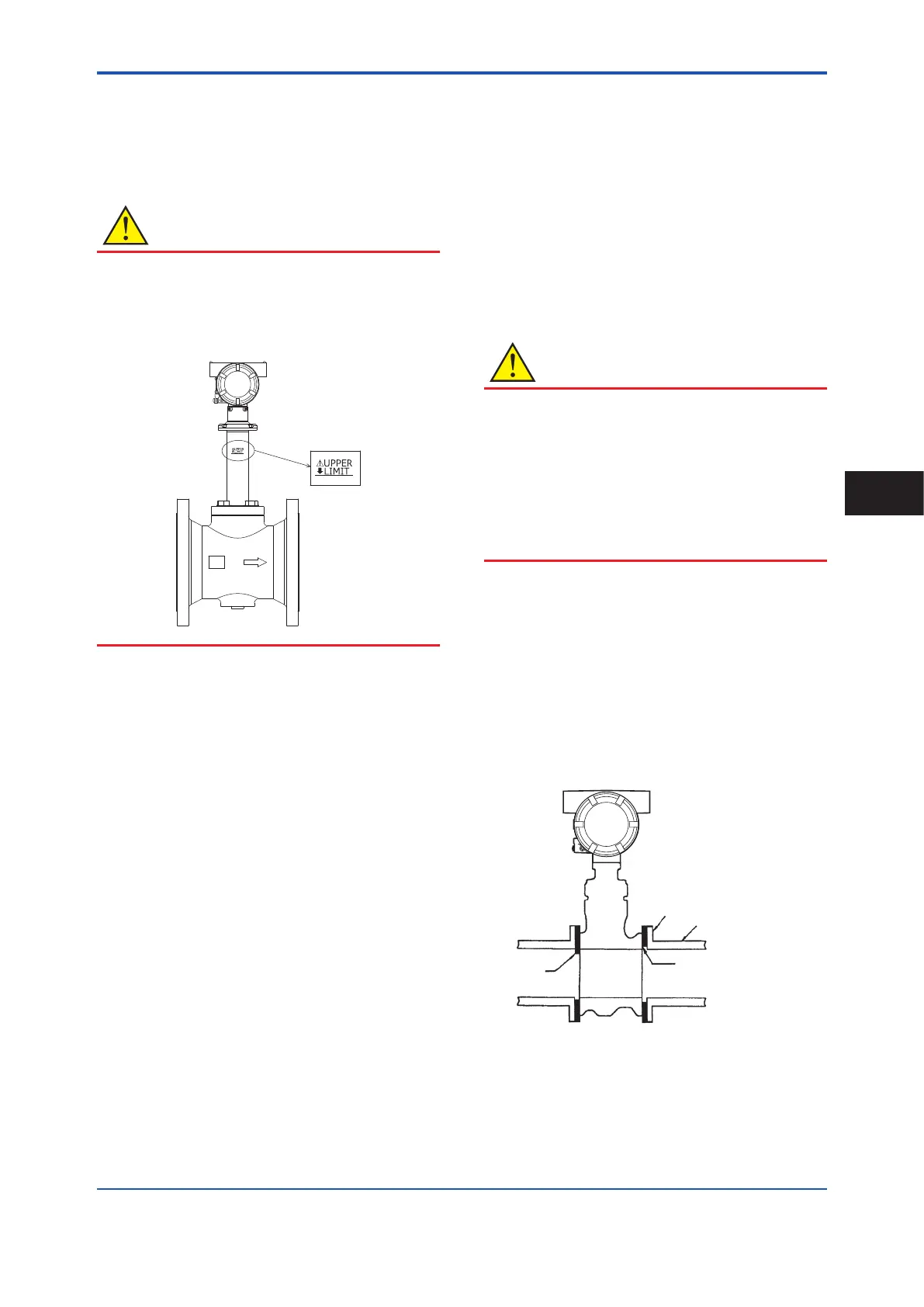
CAUTION
Strictly observe the upper limit of the heat
insulating material to prevent overheating of the
transmitter case and terminal boxes.
Seal the heat insulating material to prevent hot air
leaking from between gaps in the material.
■ Maintaining the High Temperature Type
The high temperature type uses a shedder bar
and gaskets made of materials dierent to those
used on a standard type as a countermeasure for
brittleness in high-temperature applications. When
replacing parts, specify the high-temperature type.
3.5 Mounting Procedures
When installing the vortex owmeter on piping,
ensure that the arrow indicated on the body of the
vortex owmeter matches the direction of ow of
the measured uid.
• When changing the positional relationship
between the transmitter case and the terminal
box, and the direction of ow of the measured
uid, read the maintenance manual in the
related documents indicated in Table 1.1.
1. Positioning the sensor
When installing the sensor, ensure that the
measuring pipe and adjacent pipes are concentric.
When installing a wafer type, pay attention to the
following points to ensure concentricity.
• Four collars (centering adjustment jigs for the
owmeter) are used in sets of four for the bolt
holes of anges on adjacent pipes such as
pipes of nominal diameter 15 mm to 40 mm,
nominal diameter 50 mm JIS 10K, ASME Class
150, JPI Class 150, EN PN10 to PN40, nominal
diameter 80 mm ASME Class 150, and JPI
Class 150. For this reason, use these collars to
install the sensor as shown in Table 3.2.
• When the anges of adjacent pipes have eight
bolt holes, install by using the bolt thru holes on
the vortex owmeter body shown in Table 3.2.
CAUTION
Nuts and stud bolts for piping connection parts
are not provided. These must be prepared by
the customer. They are, however, provided when
option code BL (material SUS304) is selected.
The customer should refer to Table 3.1 for
guidelines on outer diameter and length in
accordance with ange standards when preparing
stud bolts.
2. Mounting Gaskets
Gaskets for piping connection parts must be
prepared by the customer. Avoid mounting gaskets
in such a way that they protrude into the piping line
between the anges of adjacent pipes and the vortex
owmeter. Protruding gaskets may disturb the ow
of uid in the piping line and may cause error in
readings.
F0310.ai
Adjacent pipe
(No Good)
Flange of adjacent pipe
Make sure gasket does not
protrude
• Use gaskets with bolt holes to prevent
protrusion into the piping line.
• The customer should tighten gaskets at the
torque matched to the specication of the
gaskets they have prepared.
<3. Installation>
17
IM 01F07A01-01EN
Installation
3
 Loading...


