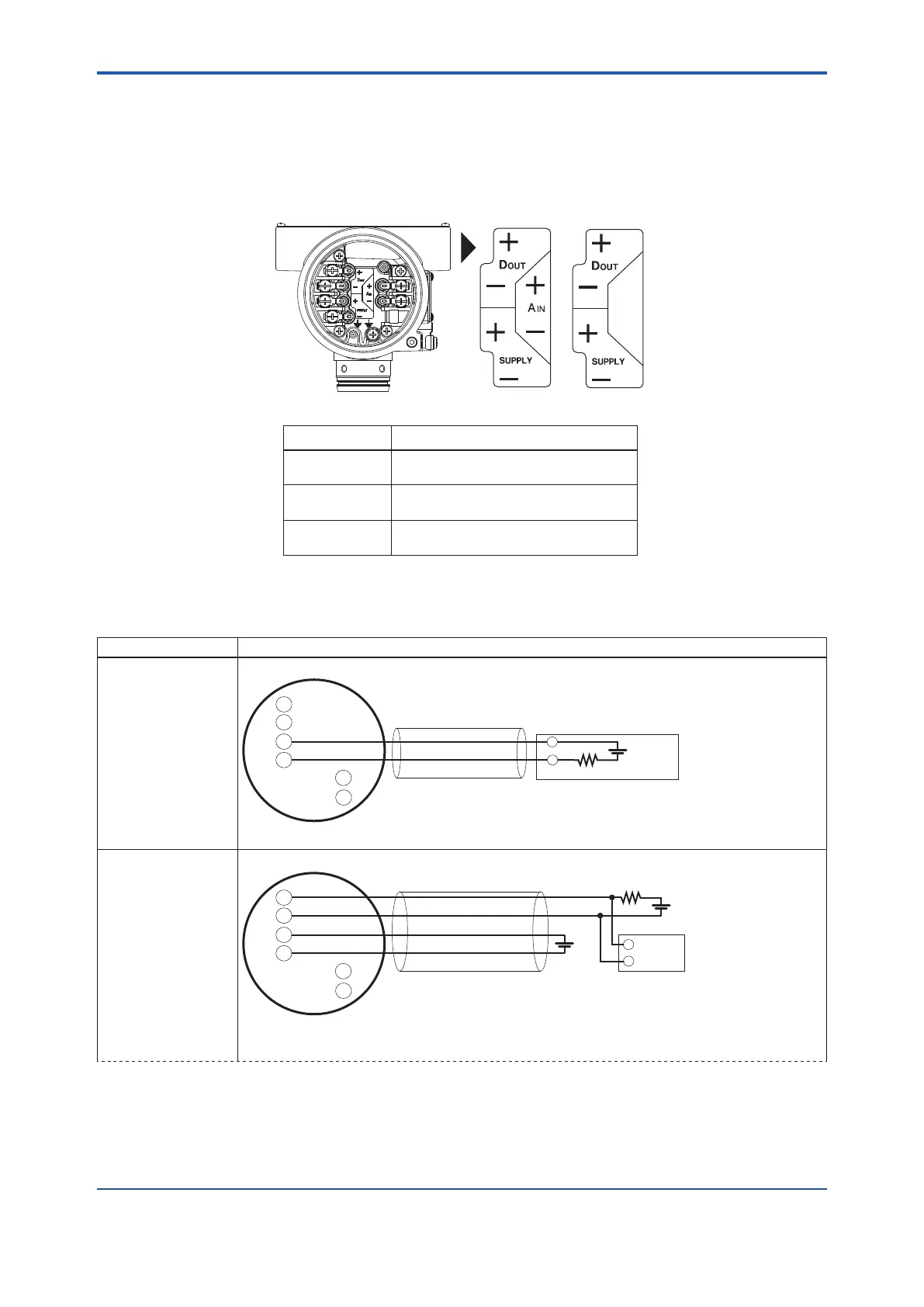
4.3 Connection Between Integral Type and Remote Transmitter
Table 4.1 shows an example of wiring between the power supply and load resistance. Figure 4.2 shows the
position of each connection terminal.
In the case of communication and input/output code JA, "SUPPLY +,-, D
OUT
+,-" is indicated on the wiring
instruction label. In the case of communication and input/output code JB, "SUPPLY +,-, D
OUT
+,-, A
IN
+,-" is
indicated on the wiring instruction label.
Integral type, remote transmitter
Terminal Symbol Application
SUPPLY +, -
D
OUT
+, -
A
IN
+, -
HART communication and analog output
Pulse/status output
Analog input
Wiring instruction label
Figure 4.2 Terminal Positions
Table 4.1 Wiring Examples
Connection Description
● Analog output
+
-
+
+
SUPPLY
D
OUT
A
IN
-
-
+
-
E1
(*1-1)
Cable resistance R1[Ω]
Cable resistance R2[Ω]
Load resistance R3 (Ω)
Distributor
(or signal conditioner card, etc.)
*1-1: 0.0244 x (R1+R2+R3) + 10.5 ≤ E1 [V] ≤ 42 (*2)
● Pulse output
Example 1:
When using 4-wire
cable
HART communication
not possible
R4
+
+
SUPPLY
D
OUT
A
IN
-
-
+
-
E1
E2
+
-
(
(*4)
(*5)
(*1-2)
(*3)
Cable resistance R1[Ω]
Cable resistance R2[Ω]
Electric
counter
*1-2: 0.0244 x (R1+R2) + 10.5 ≤ E1 [V] ≤ 42 (*2)
E2 [V] ≤ 30
<4. Wiring>
24
IM 01F07A01-01EN
 Loading...


