7.1.4 Totalizer Start and Totalizer Reset
Methods
(1) Totalizer start
To display totals, start the totalizer function.
(a) Operation using HART Conguration Tool
Set Totalizer start/stop to "1:Start".
(b) Operation using indicator
Enter the setting mode, and set parameter
"B40:01". For details on how to set from an
indicator, refer to the Communications Manual
listed in Table 1.1 Related Documents.
(Note) When the total rate is specied before shipment from the
factory, Totalizer Start/stop is set to "START".
(2) Totalizer reset
(a) Operation using HART Conguration Tool
Set Totalizer start/stop to "1:Reset".
(b) Operation using indicator
Enter the setting mode, and set parameter
"B47:01". For details on how to set from an
indicator, refer to the Communications Manual
listed in Table 1.1 Related Documents.
7.1.5 Pulse Output (Scaling)
Two modes are provided for pulse output. Set the desired
mode in parameter B20/Pulse/Status output mode.
(1) Scaled pulse
When "Scaled pulse" is selected at B20/Pulse/Status
output mode, the owrate per single pulse output
(unit is set at item C) is set.
(2) Unscaled pulse
When "Unscaled pulse" is selected at B20/
Pulse/Status output mode, the result obtained by
calculation based on the number of vortexes that
occurred from the vortex shedder is output as the
number of pulses.
The formula for the number of output pulses is as follows.
Number of output pulses per second = number of
vortexes per second / PULSE RATE setting value
For details on the calculation formula, refer to
"Calculation Formula" in the Communications
Manual listed in Table 1.1 Related Documents.
● Pulse Rate setting
Set the pulse rate at "B21/Pulse output rate".
Example: If "10" is set when the owrate unit is m
3
,
the pulse rate is expressed as 10 m
3
.
7.1.6 Setting of Burnout Setting Switch
The VY series of vortex owmeters is equipped with
a burnout function for for setting the output direction
when a hardware malfunction errors. Read Section
6.3 "Self-Diagnostic (Error Code List)". Before
shipment from the factory, the burnout output
direction is set to HIGH. However, when option
codes /C1 and /C2 are specied, the burnout output
direction is set to LOW.
To change the burnout output direction, change the
setting of the burnout setting switch on the CPU
board in the amplier.
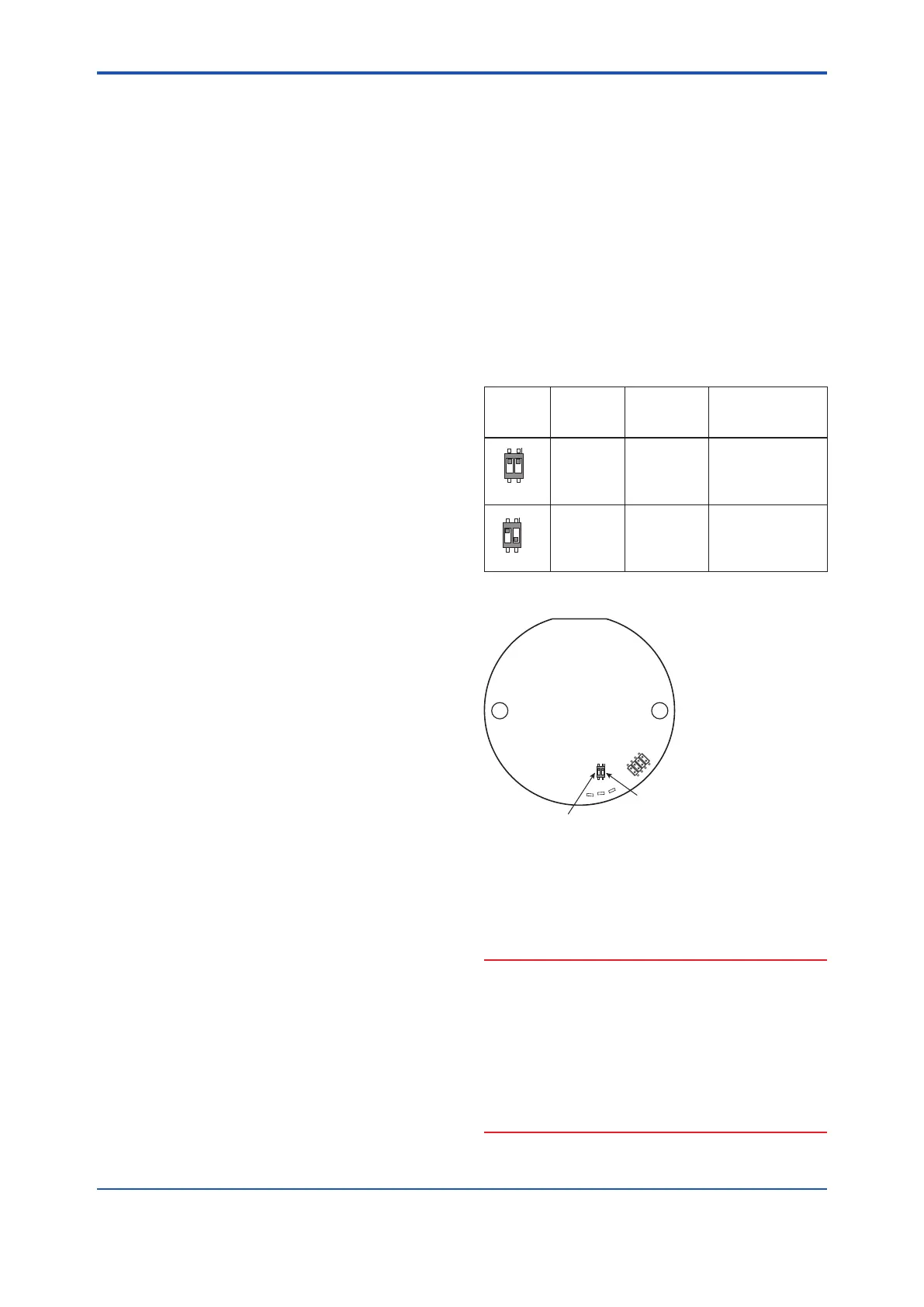
Table 7.1 Burnout Output Direction Setting Pin at
a Hardware Error
Position
of setting
pin
Burnout
direction
Burnout
output
Remark
1
2
O
N
E
L
HIGH
110% or
more (21.6
mA DC or
more)
Set to HIGH before
shipment.
1
2
O
N
E
WP BOUT
L
LOW
-2.5% or less
(3.6 mA DC or
less)
When option codes
/C1 and /C2 are
specied, the switch
is set to LOW.
F0702.ai
1 Burnout setting switch
2 Write protect setting switch
COM
P
TP2
1
2
O
N
D H
E
WP BOUT
L
Figure 7.2 Positions of Burnout and Write Protect
Setting Pins
NOTE
• The burnout setting switch (1) and write protect
setting switch (2) are located next to each other
on the CPU board in the amplier. When setting
the burnout output direction or write protect, take
care not to mistake these switches.
• To ensure safety, touch only the electrical
circuits and cables of the setting switch. Do not
touch other circuits and cables.
<7. Operation>
40
IM 01F07A01-01EN
 Loading...


