4. WIRING
CAUTION
• Lay wiring as far as possible from electrical
noise sources such as large capacity
transformers, motors, and power supplies.
• Remove the terminal cover and dustproof plug
from electrical connections before wiring.
• Be sure to waterproof the threaded sections of
cable entries.
• To prevent noise, use separate ducts for the
vortex owmeter signal cable (VY1C) and power
cables.
• Use external wiring that has an allowable
temperature 15°C or higher than the ambient
temperature.
• When using an explosion protected type, wiring
in conformance with laws and regulations is
required to maintain the explosion proong
performance of the unit.
• If a lightning protector (option code /A) is
installed, be sure to install an arrester module
during wiring. For details on the arrester module,
read 4.8 "Lightning Protector (option code: /A)".
4.1 Load Resistance and Wiring
Conditions
Table 4.1 shows the wiring methods for individual
output conditions.
(1) Analog Output
This vortex owmeter uses the same two wires for
both the signal and power supply wiring.
The power supply voltage range is 10.5 to 42
VDC (10.5 to 30 VDC, when a lightning protector
is installed and for an intrinsically safe approval
explosion protected type).
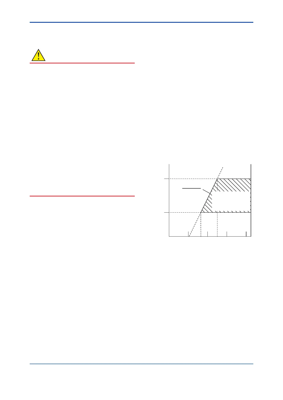
When conguring a loop, ensure that the total
resistance of the lead wire and the load, for
example, of the loop and distributor to be installed
falls within the range shown in Figure 4.1. When a
distributor is not used, connect the load resistance
to the power supply side.
4
10.5 16.6
25.2
250
600
R=
E-10.5
0.0244
Power Supply Voltage E (V)
Load resistance R (Ω)
Communication
Applicable range
HART Communication
Type
Figure 4.1 Relationship between Power Supply
Voltage and Load Resistance
(2) Pulse Output, Alarm Output and Status
Contact Output
This vortex owmeter of pulse output, alarm
output and status contact output are connected by
transistor contacts.
The rating of the contacts is 30 V, 80 mA DC.
Also, resistances are required for pulse output,
alarm output and status contact output. For details,
refer to Table 4.1.
<4. Wiring>
22
IM 01F07A01-01EN
 Loading...


