Table 3.2 (1) Installation of Wafer Type Vortex Flowmeter
Wafer type Figure
■ When a collar is used
A collar is suitable for when the
ange used is as follows.
Size mm (inch) Flange Rating
15 to 40
(1/2 to 1-1/2)
All ratings
50(2)
JIS 10K, ASME Class
150
JPI Class 150
EN PN 10, 16, 25, 40
80(3) ASME Class 150
JPI Class 150
IMPORTANT
• Use gaskets having an
inner diameter greater
than the inner diameter
of the vortex owmeter
and adjacent pipes, and
ensure that they do not
protrude into the piping
line.
• When mounting on
vertical piping outdoors,
ensure that the cable
entries face the ground
(downwards). On some
types, when both ends
are cable entries, mount
so that both sides are
horizontal to the ground.
• In the case of vertical
piping, the two collars at
the top may move after
mounting. However, there
are no problems when
using in this state.
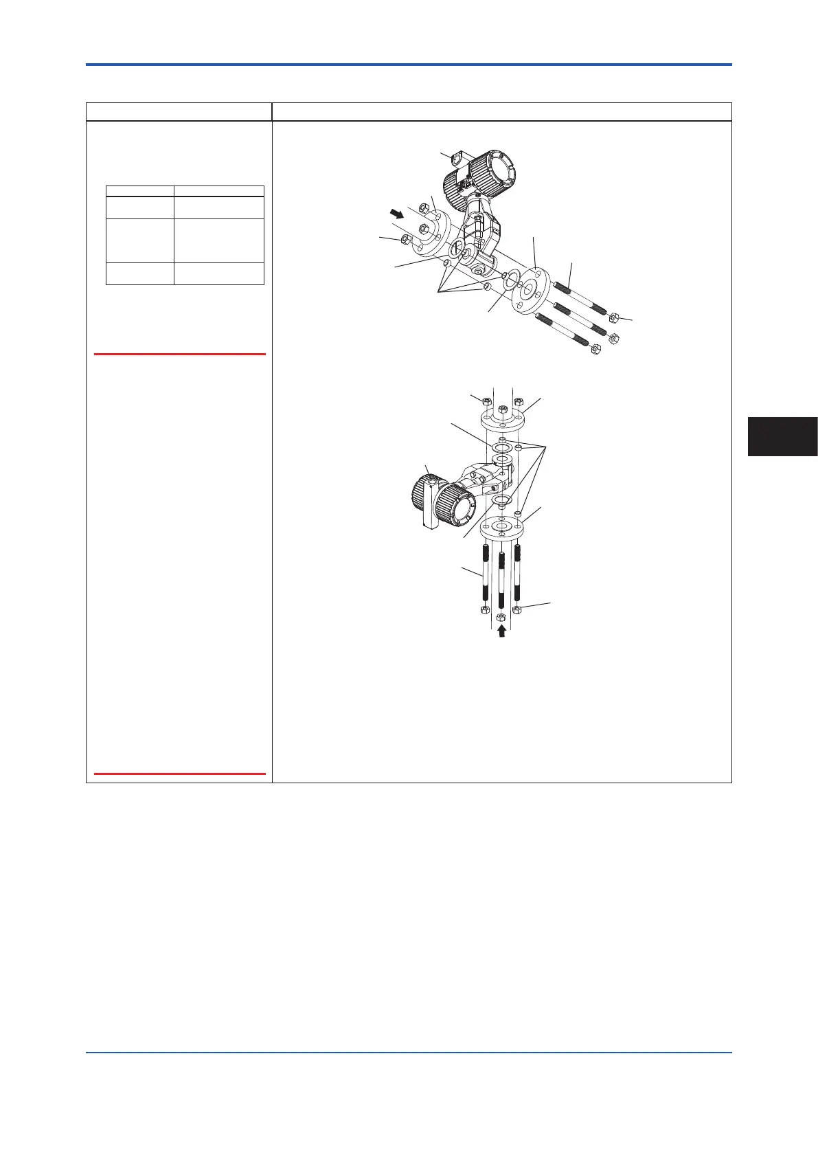
Horizontal piping installation
Flange
Nut
Gasket
Flange
Stud Bolt (4 pcs.)
Collar (4 pcs.)
Gasket
Vertical piping installation
Nut
Stud Bolt (4 pcs.)
Gasket
Gasket
Flange
Flange
(1) Pass two collars each along the two bolts on the under side of the body.
(2) Evenly tighten the stud bolts and nuts with the outer diameter surface on both sides of the
body in contact with the collars.
(3) Make sure that there are no leaks.
<3. Installation>
19
IM 01F07A01-01EN
Installation
3
 Loading...


