Connection Description
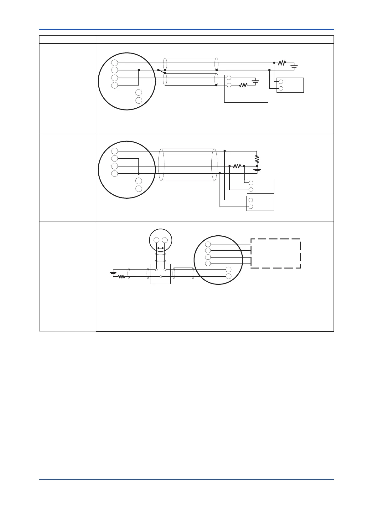
Example 3:
When using 1-wire
individually shielded
cables (*10)
One cable entry
Cable resistance R1[Ω]
Cable resistance R2[Ω]
Shielded Cable(*6)
Load resistance
R3 (Ω)
Distributor
(or signal conditioner card, etc.)
Electric
counter
SUPPLY
D
OUT
A
IN
+
-
R4
E2
(
(*3)
(*4)
(*5)
+
+
-
-
+
-
+
-
E1
(*1-8)
*1-8: 0.0244 x (R1+R2+R3) + 10.5 ≤ E1 [V] ≤ 42 (*2)
E2 [V] ≤ 30
Example 4:
When using 3-wire
cable (*10)
HART communication
not possible
One cable entry
+
+
SUPPLY
D
OUT
A
IN
-
-
+
-
R4
E1
+
-
(*1-9)
(*3-1)
+
-
R3
(
(*5)
Cable resistance R1[Ω]
Cable resistance R2[Ω]
Electric
counter
Recorder
,
etc.
*1-9: 0.0244 x (R1+R2+R3) + 10.5 ≤ E1[V] ≤ 30
● Analog input
When using 2-wire cable
One cable entry
+
+
SUPPLY
Cable
Cable
Cable
D
OUT
A
IN
-
-
+
-
-
+
R5
E3
Vext
(*8)
(*8)
(*8)
*1-10)
For details about the
D
OUT
and SUPPLY
connections, see the
wiring examples
provided above.
Vortex Flowmeter
*1-10: Vext + (R5+R6+R7) x I+3.8 ≤ E3 [V] ≤ 42 (*2)
Vext: Minimum operating voltage of external device
I: Maximum current owing in loop
Voltage between A
IN
terminals is 3.8 V typ with loop current of 20 mA.
Calculate with 4.2 V if used at low temperature below 0°C.
*2: If lightning protector (option code /A) is installed, calculate with maximum voltage of 30V.
*3: The owmeter requires a power supply with a maximum output current of E2/R4 or more.
*3-1: The owmeter requires a power supply with a maximum current of E1/R4+22.4 mA or more.
*4: To avoid the inuence of external noise, use an electric counter that suits the pulse output frequency.
*5: Resistor is not necessary in case of an electric counter that can receive the contact pulse signal directly. (R4 is in open state.)
*6: Separate shielded cables are required for SUPPLY and D
OUT
.
*7: Communication cannot be performed if shielded cables are not used, but simultaneous analog and pulse output is possible.
*8: Add all cable resistance values on the positive side to obtain R6 (Ω).
Add all cable resistance values on the negative side to obtain R7 (Ω).
*9: When using simultaneous analog/pulse output, communication may be more susceptible to noise than when using analog
output only.
*10: This example describes the wiring method when reusing existing digitalYEWFLO wiring cables. For a new installation, use
2-wire individually shielded cables.
<4. Wiring>
26
IM 01F07A01-01EN
 Loading...


