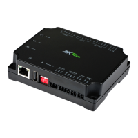
C2-260/inBio2-260 Access Control Panel
User Manual
Page | 14 Copyright©2020 ZKTECO CO., LTD. All rights reserved.
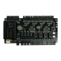
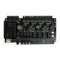
Control Panel Connection Terminals 3.4
C2-260/inBio2-260 Terminal connection diagram
Description of the terminals:
1. The auxiliary input may connect to infrared body detectors, fire alarms, or smoke detectors.
2. The auxiliary output may connect to alarms, cameras or doorbells, etc.
3. PC RS485 indicates the RS485 cable is connected to the PC through this port. The RS485 Reader
port can be connected externally to RS485 reader. Note: Only inBio2-260 supports to connect the
FR1200 readers.
4. Restore factory setting: Put number 4 of DIP switch to ON position three times in 5 seconds, the
device will reboot, and the IP address will restore to the default (192.168.1.201).
5. The terminals above are set through the relevant access control software. Please see the respective
software manual for further details.
#1 Door
Output
Input
#2 Door
RS485 Reader
DIP Switch
PC RS485
 Loading...