EasyManuals Logo

Zmotion ZMC420SCAN User Manual

Default Icon
68 pages
To Next Page IconTo Next Page
To Previous Page IconTo Previous Page
Page #37 background imageLoading...
Page #37 background image
ZMC420SCAN Motion Controller Hardware Manual V1.5
Isolation
cross skeleton
Connector
Crystal head with iron shell
Cable material
PVC
Cable length
Less than 100m
Use RJ45 network cable connection method:
When installing, hold the crystal head that is with the cable and insert it into the RJ45
interface until it makes a "click" sound (kada).
In order to ensure the stability of communication, please fix the cables with cable ties.
When disassembling, press the tail mechanism of the crystal head, and pull out the
connector and the module in a horizontal direction.
Please use tube-type pre-insulated terminals and cables with appropriate wire
diameters to connect the user terminals.
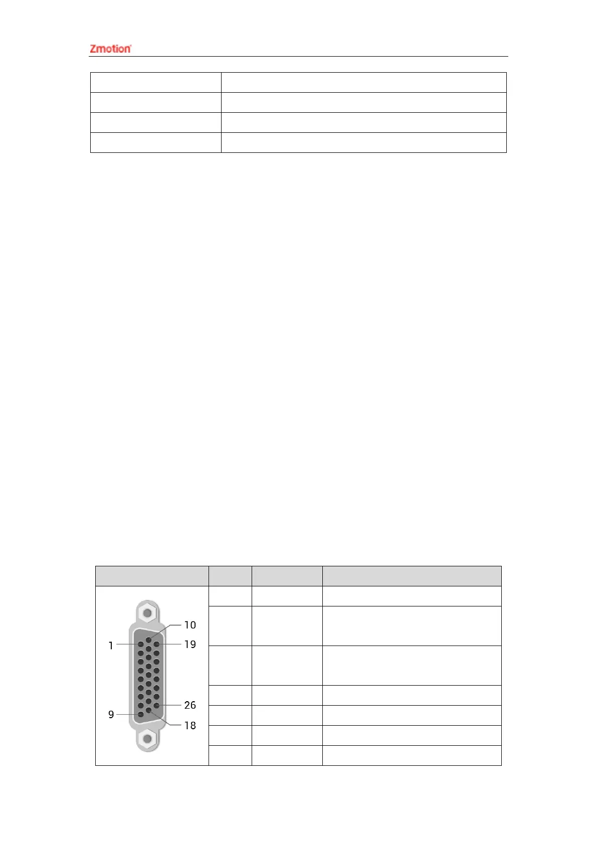
3.11. AXIS Differential Pulse Axis Interface
This product provides 4 local differential pulse axis interfaces, each interface is a
standard DB26 female socket. Each terminal provides 0V and +5V output, which can
provide 5V power for the encoder.
Before the axis is used, use ATYPE instruction to configure the axis type.
Interface Definition
Interface
Pin
Signal
Description
1
EGND
Negative pole of IO 24V power
2
IN24-
29/ALM
General input (recommended as
driver alarm)
3
OUT12-
17ENABLE
General output (recommended as
driver enable)
4
EA-
Encoder differential input signal A-
5
EB-
Encoder differential input signal B-
6
EZ-
Encoder differential input signal Z-
7
+5V
Positive pole of 5V power of

Table of Contents

Other manuals for Zmotion ZMC420SCAN

Questions and Answers:

Question and Answer IconNeed help?

Do you have a question about the Zmotion ZMC420SCAN and is the answer not in the manual?

Zmotion ZMC420SCAN Specifications

General IconGeneral
BrandZmotion
ModelZMC420SCAN
CategoryController
LanguageEnglish