ZXR10 WAS (V1.0) W140A Outdoor Wireless Access Point / Bridge
Professional Installation Instruction Manual
2-14
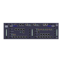
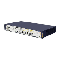
Fig. 2.3-3 The W140A Backplane
3. Installing the antenna: Fix the antenna stand to the left and right locks in the
W140A using a U-shape fixture. Do not screw it too tight. Then fix the omni
antenna to the antenna stand using a U-shape clamp.
Note:
● All the antennas must be clamped on the metallic casings, to ensure that all the
other parts in the antennas do not bear any weight.
● The antenna feeder shall go through the left and right locks of the W140A to make
it look nicer.
4. Installing the W140A: Securing the W140A with a backplane to the mounting
plane on the wall with reference to the three fastening holes in the backplane and
by using the fastening screws.
5. Fixing the antenna: Turn the antenna stand to place the antenna in an optimum
position. Then tighten the U-shape fixture to fix the antenna stand firmly.
6. Connecting the cable: Interconnect the U-interface cable led out from the
distribution box with the twisted pairs of the W140A, and carry out water-proof
and anti-aging treatment. Connect and tighten the cable connectors of the
antenna with the antenna interface of the W140A, and make sure that they are
waterproof.
2.3.2.2
Pole-Mounted Mode
The pole-mounted mode is suitable for installing an omni antenna in an installing
support B. Two models of installing support are available: 150 mm-gauge and 230
mm-gauge.
 Loading...