Chapter 8 Basic Setting
XGS2210 Series User’s Guide
99
8.11 Stacking
Stacking is directly connecting Switches to form a larger system that behaves as a single Switch or a
virtual chassis with increased port density.
Figure 76 Switch Stacking Concept
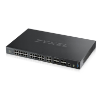
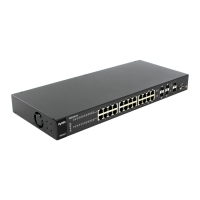
The last two SFP ports of your Switch are dedicated for Switch stacking. These are the Switches that
support stacking at the time of writing.
Note: Up to 2 Switches per stack are allowed.
You can manage each Switch in the stack from a master Switch using its web configurator or console.
Each Switch supports up to two stacking channels. Use the master Switch to assign a ‘slot ID’ for each
‘linecard’ non-master Switch. ‘Slot’ refers to a Switch in the ‘virtual chassis’ stack.
The advantages of stacking are:
• High port density - for example, two 48-port Switches can become one 96-port logical Switch
• Centralized management - log into a single IP address of the master switch to control all Switches in
the stacking system using the web configurator, CLI, SNMP or FTP
• Redundancy - Data redundancy allows traffic to be forwarded even if one Switch in the stack fails.
Management redundancy lets you still manage the stack even if one Switch in the stack fails
• Modularity and hot-swappable - you can add, remove, or replace Switches to increase or decrease
the stack with minimum disruption to ongoing network traffic.
You can build a Switch stack using a ring or chain topology. In a ring topology, the last Switch is
connected to the first.
Domain-List This field displays whether the Switch obtains a list of domain names from the DHCP server.
Information
Refresh
Minimum
This field displays the time interval (in seconds) at which the Switch exchanges other configuration
information with a DHCPv6 server again.
Table 35 Basic Setting > IPv6 > IPv6 Configuration > DHCPv6 Client Setup
LABEL DESCRIPTION
Table 36 Switch Stacking
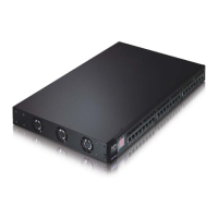
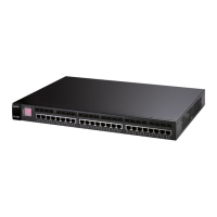
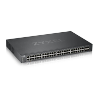
MODELS WITH STACKING SUPPORT
XGS2210-28
XGS2210-28HP
XGS2210-52
XGS2210-52HP
 Loading...


