247Security Inc. | 4400 North Point Parkway, Suite # 158, Alpharetta, GA 30022, USA | 1-866-693-7492 | www.247securityinc.com
ZEUS mDVR
USERS MANUAL
14
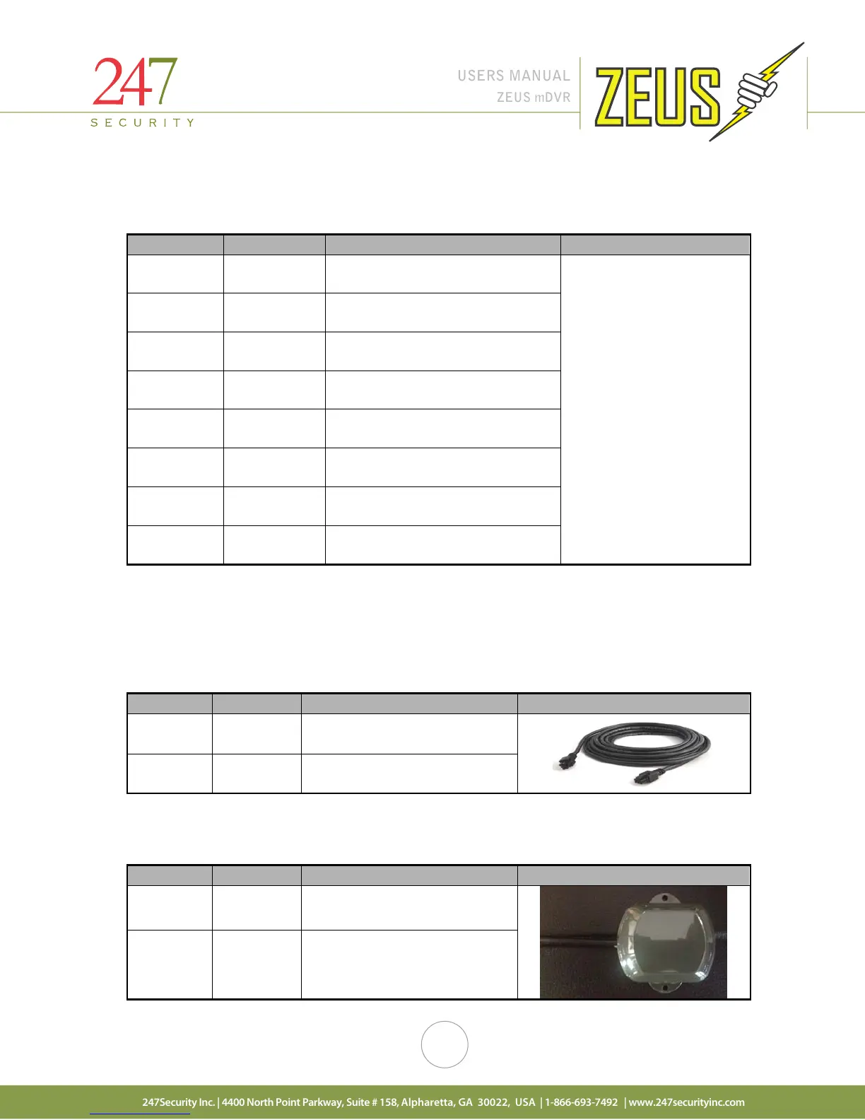
2.2.3 SENSOR / ALARM CABLE
A 15ft sensor / alarm cable is provided to connect the 4 digital inputs, 1 digital output and motion
sensor signals to the GP I/O port of the DVR.
Brown Input DI_1
Connects to Digital Input 1 of GP
I/O connector (Pin 1)
White/
Green
Input DI_2
Connects to Digital Input 2 of GP
I/O connector (Pin 2)
Green Input DI_3
Connects to Digital Input 3 of GP
I/O connector (Pin 3)
Orange
Input DI_4
Connects to Digital Input 4 of GP
I/O connector (Pin 4)
Orange
Motion
Sensor
Connects to Motion Sensor of GP
I/O connector (Pin 5)
Output DO_3
Connects to Digital Output 3 of GP
I/O connector (Pin 6)
Blue GND
Connects to GND of GP I/O
connector (Pin 7)
White/
Blue
GND
Connects to GND of GP I/O
connector (Pin 8)
2.2.4 CAMERA CABLE
STP (shielded twisted pair) cable is the standard and will use 2x3 Molex plugs for connections making
the installation simple and straight forward. The cable connectors are keyed so they cannot be connected
incorrectly. Connect one end of the cable to one of the available camera inputs on the DVR and the other end
into the camera.
6-Pin
Molex
Connects to DVR
6-Pin
Molex
Connects to camera
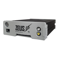
2.2.5 GPS MODULE & CABLE
An internally mounted GPS module attaches to a 15ft cable to the back of the DVR using a 2x3 Molex
camera cable. This is an RS-232 connection.
Connector Signal Description Picture
6-Pin
Molex
connector on DVR
6-Pin
Molex
Connects to GPS