12
PRINTING AREA
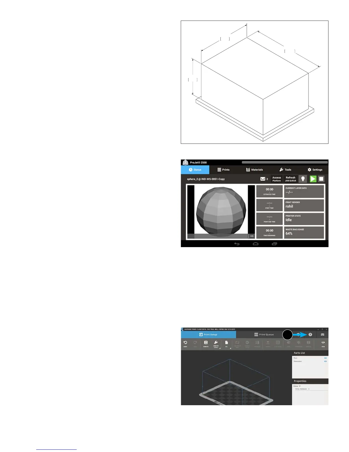
The actual area that you can print a job consists of the length x width
plus the maximum height of a job. This diagram illustrates exactly
what the maximum build area is for the ProJet 2500.
3D PRINTER SYSTEM COMPONENTS
For 3D printer system requirements, consult the Facility
Requirements Guide.
288mm
11.34in
212mm
8.35in
144mm
5.67in
Need updated diagram from Wilsonville
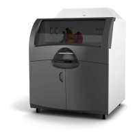
User Interface
The User Interface consists of a tablet built into the top of the printer
to the right. There are ve main screens that contain sub menus that
allow the user to do a variety of things through the tablet. These ve
screens and their menus are:
1. Status Screen
• Current Layer Info
• Print Sender
• Printer State
• Waste Bag Usage
2. Prints Screen
• Opens Print Queue for the Printer
3. Materials Screen
• Material Status
• Part Message
• Support Message
4. Tools Screen
• Diagnostics
• Material Change Wizard
• Printer Info
• Access Platform
• Play
• Refresh Job Queue
• Email Notication
• Printer Usage
• Printer Shutdown
5. Settings Screen
• Admin Settings
• Email Alerts
• Alert Settings
• Network Settings
• Printer Connection
These are the only things that can be done through the UI. All other
operations must be done through a computer/laptop using the
3DSPRINT
TM
software. For complete information on using
3DSPRINT the Help (6) le can be accessed through the icon in
the software.
6