13
9.3. Set up andConnections
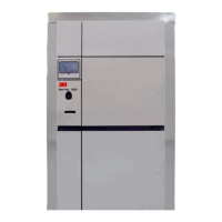
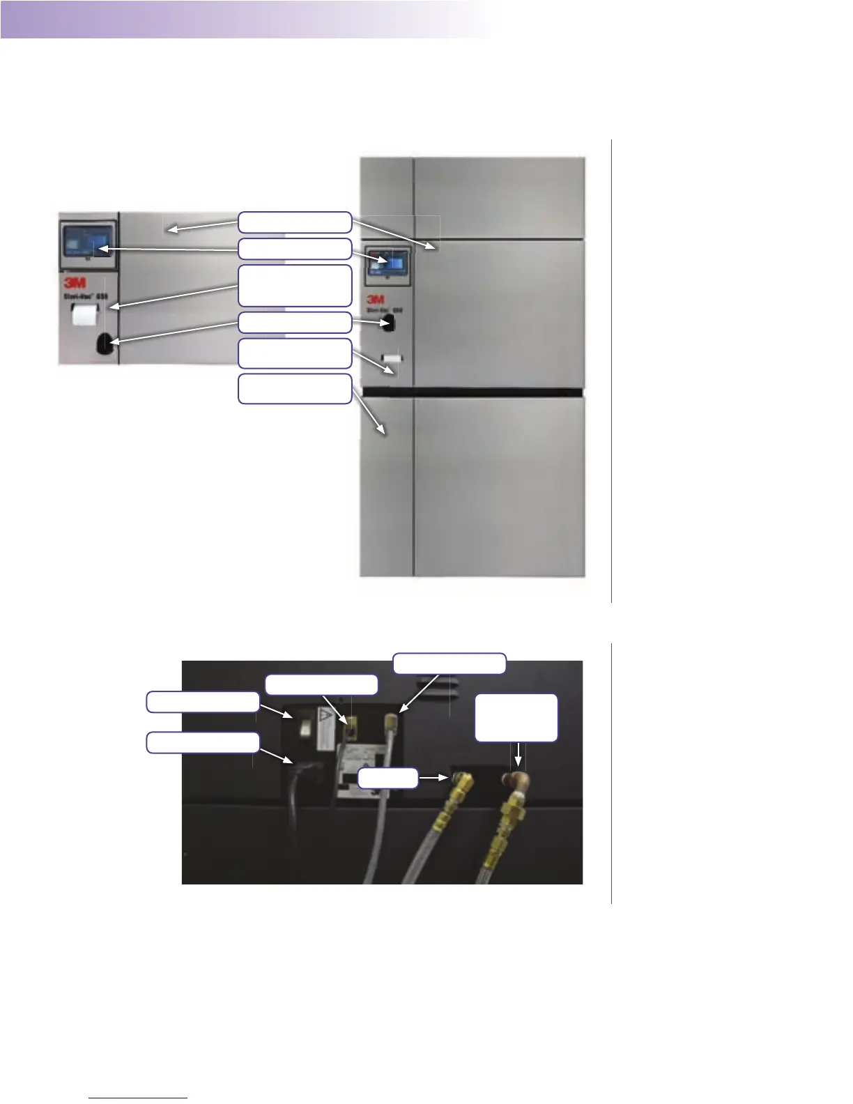
Figures 3- 7illustrate the components and connections for the 3M™Steri-Vac™ Sterilizer/Aerator Series, Models GS5and GS8. Table 2contains additional details regarding specific
components and connections for the GS Series Models GS5andGS8.
ChamberDoor
Touch Screen &Display
Water Reservoir,
Printer&USB Ports
AccessDoor
Cartridge ScannerBay
Printer & USB Ports
AccessDoor
Water Reservoir
AccessDoor
Figure3.
Front View 3M™Steri-Vac™
S
terilizer/Aerator GS Series,
Models GS5&GS8
1. PowerCord
2. PowerSwitch
3. Ethernet(optional)
4. Abator(optional)
6. Chamber Exhaust
(Ethylene Oxide
VentLine)
5. AirInlet
Figure4.
Left Side Connections -
3M™S
teri-Vac™ Sterilizer/
Aerator GSSeries
 Loading...