Aprisa SRx User Manual 1.3.0
Power
The external power source must be connected to both the A and B Molex 2 pin male power connectors
located on the protected station front panel. The A power input powers the A radio and the B power input
powers the B radio.
The protection switch is powered from the A power input or the B power input (whichever is available).
The maximum combined power consumption is 35 Watts.
The Aprisa SR+ Protected station has two DC power options, 12 VDC and 48 VDC.
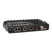
12 VDC
The 13.8 VDC nominal external power source can operate over the voltage range of +10.5 to +30 V DC
(negative earth).
An example of the 12 VDC option part number is:
4RF SR+, PS, 400-470 MHz, SSC, Half Duplex, 2E2S, EN, STD
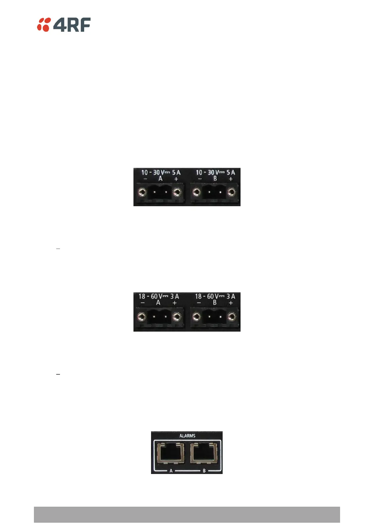
48 VDC
The 48 VDC nominal external power source can operate over the voltage range of 18 to 60 V DC (floating).
An example of the 48 VDC option part number is:
4RF SR+, PS, 400-470 MHz, SSC, Half Duplex, 2E2S, EN, 48VDC
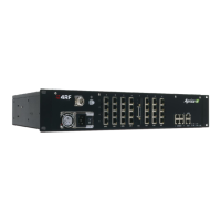
Alarms
The protection switch provides access to both the A radio and B radio Alarm Interfaces (see ‘Alarm
Interface Connections’ on page 298 for the connector pinout).