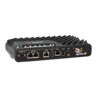
Aprisa SRx User Manual 1.3.0
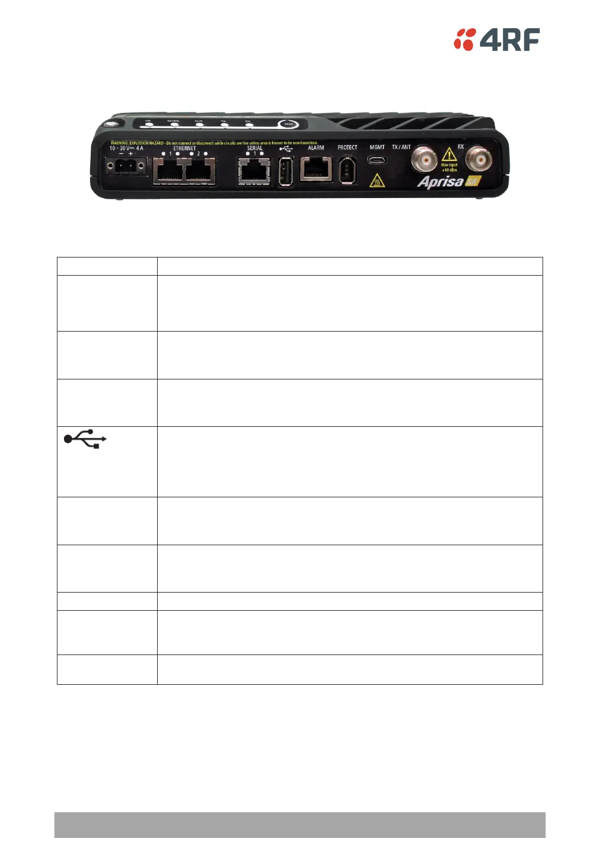
Front Panel Connections
All connections to the radio are made on the front panel. The functions of the connectors are (from left to
right):
+10 to +30 VDC (negative ground) DC power input using Molex 2 pin male screw
fitting connector.
AC/DC and DC/DC power supplies are available as accessories. See ‘External
Power Supplies’ on page 59.
Integrated 10Base-T/100Base-TX layer-3 Ethernet switch using RJ45 connectors.
Used for Ethernet user traffic and product management.
See ‘Ethernet > Port Setup’ on page 111.
One port of RS-232 serial using RJ45 connector.
Used for RS-232 asynchronous user traffic.
See ‘Serial > Port Setup’ on page 106.
Host Port using a USB standard type A connector.
Used for software upgrade and diagnostic reporting and optional: 1x RS-232
asynchronous port with USB to RS-232 converter.
See ‘Radio Software Upgrade’ on page 292 and ‘Maintenance > General’ on page
153.
Alarm Port using a RJ45 connector.
Used for two alarm inputs and two alarm outputs.
See ‘Hardware Alarms Interface’ on page 316.
Management Port using a USB micro type B connector.
Used for product configuration with the Command Line Interface.
See ‘Connecting to the Management Port’ on page 259.
Protect port. Used for Protected Station operation.
TNC, 50 ohm, female connector for connection of antenna feeder cable for half
duplex RF operation or the Transmit connection to an external duplexer.
See ‘Coaxial Feeder Cables’ on page 51.
TNC, 50 ohm, female connector for the Receive connection to an external
duplexer.