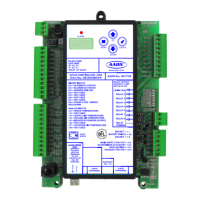
RSM STATUS
VCC-X Operator Interface SD
68
RSM-VFD & HP #1-#4 Status Screen
Index
The available Status Screens for the RSM-VFD & HP Modules are
listed by sequential screen number. The following is a list of all the
RSM Status Screens in numerical order with a brief listing of the
Status features available on each screen. The A1 & A2 notations
will be B1 & B2 for RSM #2, C1 & C2 for RSM #3, and D1 & D2
for RSM #4.
Screen #1 RSM Compressor A1 & A2
On/Off & Current Position
Screen #2 RSM Coil Temperature, Coil Setpoint,
and Suction Pressure
Screen #3 RSM Coil Temperature 1,
Superheat 1, Expansion Valve 1 Position
Screen #4 RSM Coil Temperature 2,
Superheat 2, Expansion Valve 2 Position
Screen #5 RSM Head Pressure Reading, Head Pressure
Setpoint, and Condenser Signal
Screen #6 RSM HP Coil Temperature 3,
Superheat 3, Expansion Valve 3 Position
Screen #7 RSM HP Coil Temperature 4,
Superheat 4, Expansion Valve 4 Position
Screen #8 RSM HP Leaving Water Temperature,
Proof of Flow
Screen #9 RSM No Alarms / Active Alarms
Status Screens - General Procedures
From any menu screen, press <STATUS>. The Unit Selection
Screen, shown below,
will appear requesting that you enter the unit
ID number.
Enter Unit Address
Then Press Enter
Selected Unit#: XXXX
No Communication
Enter the correct unit ID number of the Controller that the RSM
Module(s) are connected to and press <ENTER>. Once communica-
tion is established, the No Communication message will go away
and the Press Down message will appear. Then
press <>. You will
then see the Status Selection Screen(s) below:
VCC-X Status
RSM-VFD & HP Status
RSM-DIGITAL Status
Select & Press Enter
Use the arrow keys to move the cursor to select RSM-VFD Status.
You will then see the Status Selection Screen(s) that follow:
RSM #1
RSM #2
RSM #3
Select & Press Enter
RSM #4
Select & Press Enter
Use the arrow keys to move the cursor to select which Module’s
Status Screens you wish to view. Then press
<ENTER>. The fi rst
Status Screen will appear.
Press <> to scroll through the screens.
RSM Status Screen #1 - Compressor 1 & 2 En-
able and Current Position
RSM #1-4 Status
Compressor 1: ON/OFF
Compressor 2: ON/OFF
Comp Position: 0%
Line 2 Compressor 1 Enabled or Disabled
Current status of the fi rst Compressor.
Line 3 Compressor 2 Enabled or Disabled
Current status of the second Compressor.
Line 4 Current Position
Current position of the Modulating Compressor.
RSM Status Screen #2 - Coil (Saturation)
Temp & Setpoint & Suction Pressure
RSM #1-4 Status
Coil Temp: 0.0ºF
Coil Setpt: 0.0ºF
Suction Pr: 0 PSI
Line 2 Coil (Saturation) Temperature
If a Suction Pressure Transducer has been installed and
confi gured on the unit, the calculated Evaporator Coil
Suction (Saturation) Temperature will appear on this
line. If not, this line will display 0°F.
Line 3 Coil (Saturation) Temperature Setpoint
During DX dehumidifi cation, compressor(s) will be
staged/modulated to maintain this Coil Suction
(Saturation) Temperature Setpoint. If indoor humidity
reset of the Coil Setpoint has been confi gured, this will
be the current calculated setpoint.
Line 4 Suction Pressure
This is the current Suction Pressure.
RSM-VFD & HP Status Screens

 Loading...