MODULAR SERVICE TOOL SD
10 VCC-X Operator Interface SD
Modular Service Tool Keys
Operator Interfaces
In order to confi gure and program the VCC-X Controller, you must
have an Operator’s Interface or a personal computer with the Prism
2 computer front-end software installed. Two different Operator
Interfaces are available for programming of the VCC-X Controls
System—the Modular Service Tool SD and/or the System Manager
TS. These devices allow you to access the status and setpoints of
any controller on your communications loop. This manual describes
the Modular Service Tool SD. If using the System Manager TS II,
please see the System Manager TS II Technical Guide. If using Prism
2, please see the Prism 2 Technical Guide.
The Modular Service Tool allows you to view any input or output
status and change any setpoint to fi ne-tune the operations of the
total system. All keypad operations are simple and straightforward,
utilizing non-cryptic plain English messages.
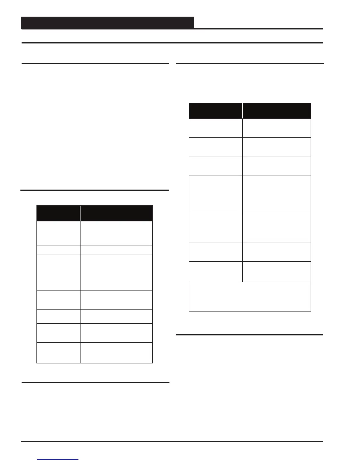
Table 1: Keypad Descriptions
Table 2: Button Descriptions
Display Screens & Data Entry Keys
See the chart below for a list of the keypad descriptions and functions.
Keypad
Description
Function
ESC
Use this key to exit from screens or
from data entry or to return to the
Main Screen from any screen in the
system.
ENTER
Use this key to enter a new value.
Clear
If a data entry mistake is made,
press this key to clear the data entry
fi eld and start over. This key also
turns off the power to the Service
Tool when on the
Main Screen
Minus
If a setpoint with a negative value
is required, press this key for the
minus sign.
DEC
Press this key when entering data
that requires a decimal point.
Use these keys to change values
in the Confi guration Screens as
prompted.
Use these keys to step backward or
forward through the screens.
Mode Selection Buttons
The Modular Service Tool is provided with “Mode Selection But-
tons.” These buttons give you instant access to the specifi c mode
desired without having to scroll through several menu screens to
get there.
Button
Description
Function
STATUS
Pressing this button takes you
directly to the controller
“Status” screens.
SETPOINTS
Pressing this button takes you
directly to the controller
“Setpoints” screens.
SCHEDULES
Pressing this button takes you
directly to the controller
“Schedules” screens.
OVERRIDES
Pressing this button takes you
directly to the controller “Over-
rides” screen. See the “Override
Button” section on page 21 for a
description of this function.
See Note 1 below.
ALARMS
Pressing this button takes you
directly to the controller
“Alarms” screen. See the “Alarms
Button” section on page 20 for a
description of this function.
CONFIGURATION
Pressing this button takes you
directly to the controller
“Confi guration” screens.
BALANCE-TEST
Pressing this button takes you
directly to the controller
“Balance-Test” screens.
NOTE:
(1) The Modular Service Tool will only search the Overrides
one loop at a time. You must enter the Loop number and the
MiniLink PD unit ID (60).