VCC-X Operator Interface SD
SYSTEM CONNECTION
9
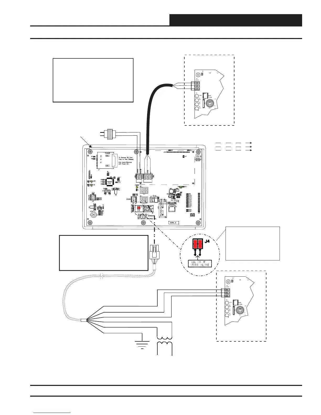
Stand Alone Connection
Use Supplied Modular Cable
With Stripped Ends For
Connection To Terminal Block
And Transformer
WHITE (T)
DRAIN WIRE (SHLD)
BLACK (R)
RED (24 VAC)
BROWN (GND)
GREEN (GND)
Class 2 Transformer
Rated For 6 VA Minimum
Controller Board
T
SHLD
R
NOTE: If Desired A Power/Comm Board As
Used With The Networked System Can Be
Installed And Wired Instead Of Using The
Pigtail Cable Wiring Shown Below. See The
Networked System Wiring Diagram For
Details.
Modular System
Manager SD
Back View
NOTE: For Stand-Alone
Installations (No CommLink
or MiniLink), All TERM
Jumpers Must Be ON.
For All Applications With
CommLink(s) Or MiniLink(s),
All Jumpers Must Be OFF.
4
GB
NOTE: You Can Use The Three
Conductor Communications Terminal
Block or a Modular Connection to
Connect to the Controller Board.
One or the Other Option Can Be Used,
Not Both. Alternatively, for Network
Connections, A Power Comm Board
Can Be Used. See Note Below.
Line
24VAC
R
SH
T
R
SH
T
R
SH
T
R
SH
T
All Comm Loop Wiring Is
Straight Through
Local Loop
RS-485
9600 or 57,600
Baud
24VAC Transformer
(By Others)
Rated for 6 VA
GND
Controller Board
T
SHLD
R
Figure 6: Modular System Manager SD - Stand Alone